P/N 960-100940R_Rev. A © 2016, JCM American Corporation
Section 2 GEN5™ Series Printer Installation
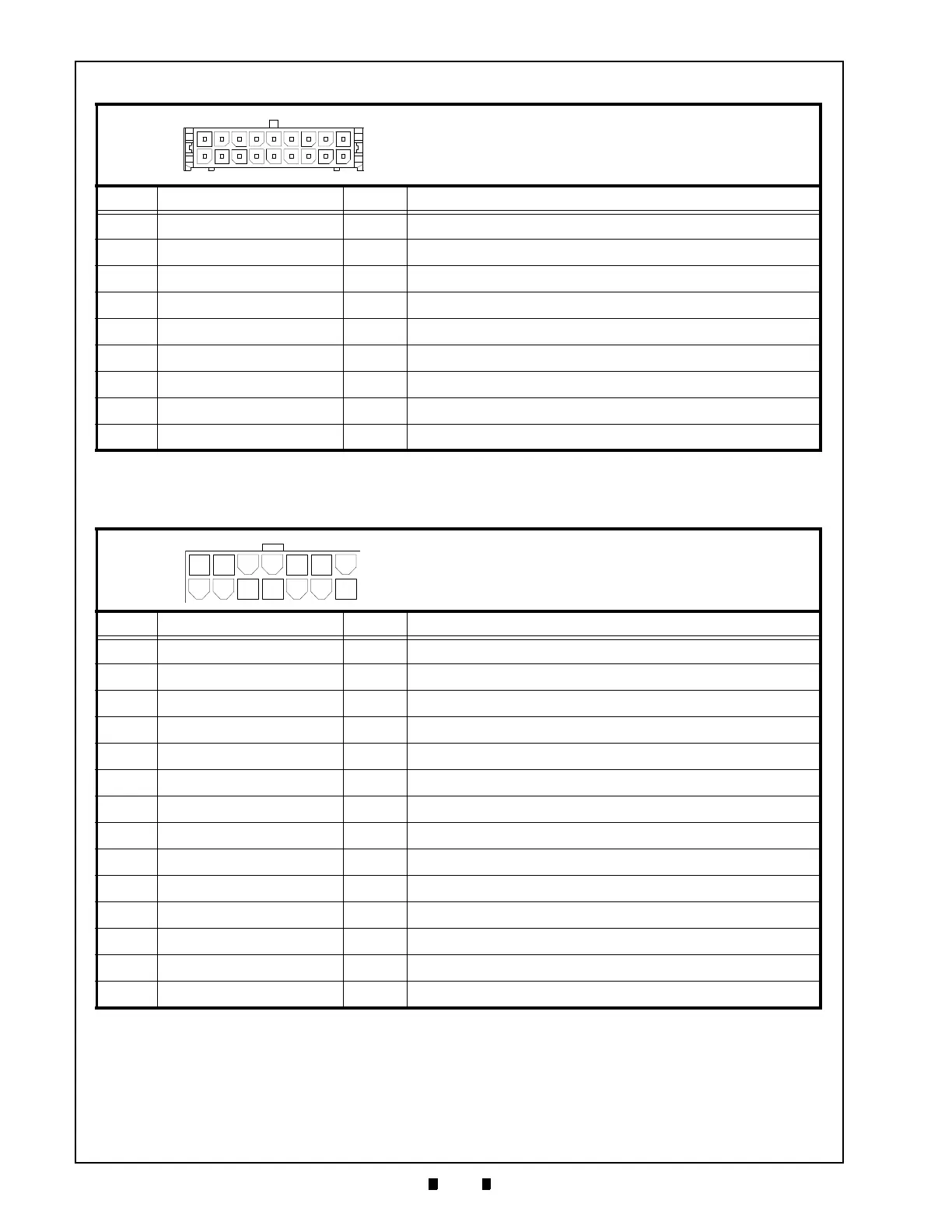
RS232C Connector Pin Assignments
Table 2-5 lists the GEN5 RS232C Connector Pin Assignments.
10 RX2 I Receive 2, RS232C
11 TX2 O Transmit 2, RS232C
12 RX1 I Receive 1, RS232C
13 TX1 O Transmit 1, RS232C
14 TX1 O Transmit 1, Netplex
15 RX1 I Receive 1, Netplex
16 DNGD - Ground
17 VBUS - USB+5V
18 No Connection - No Connection
Table 2-5 GEN5 RS232C Connector Pin Assignments
Pin No. Signal Name I/O Function
1 MRESET MRESET
2 No Connection
3 No Connection
4 No Connection
5DGND
-
Ground
6+24V DC
-
+24V DC Power Supply
7DGND
-
Ground
8+24V DC
-
+24V DC Power Supply
9 Switched +24V
-
Switched +24V(Bezel)
10 DGND
-
Ground
11 RX1 I Receive 1 - RS232C
12
TX1
O Transmit 1 - RS232C
13 DTR
-
DATA Terminal Ready
14 RTS
-
Request to Send
Table 2-4 GEN5 Base Port Connector Pin Assignments (Continued)
Pin No. Signal Name I/O Function
Connector: 43025-1800 (MOLEX)
Mate: 43045-1812 (MOLEX)
Coil Interface Connector/RS232C/USB
Connector: 39-01-3149 Mini-Fit Jr. (MOLEX)
Mate: 39-01-2140 Mini-Fit Jr. (MOLEX)
RS232 Power/COMM Port Connector/Coil Interface
 Loading...