P/N 960-100940R_Rev. A © 2016, JCM American Corporation
Disassembly/Reassembly GEN5™ Series Printer Section 4
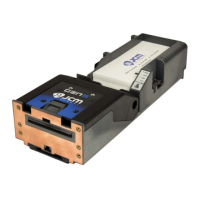
Upper Presenter Motor Removal
To remove the Upper Presenter Motor, proceed as
follows:
1. Remove two (2) screws located along the left
side cover (Figure 4-7 a
1
and a
2
).
2. Lift the Cover from the Print Assembly.
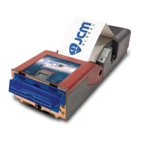
3. Remove two gears (Figure 4-8 a
1
and a
2
).
4. Remove one (1) e-clip (Figure 4-8 b) and the
Platen roller
gear (Figure 4-8 c).
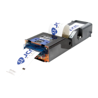
5. Remove four (4) flat head screws holding the left
side (Figure 4-9 d
1
thru d
4
) and the single Pan
Head screw from the inside of the left bracket
(Fig
ure 4-9 e).
6. Slide the Upper Presenter Motor out of the
Frame.
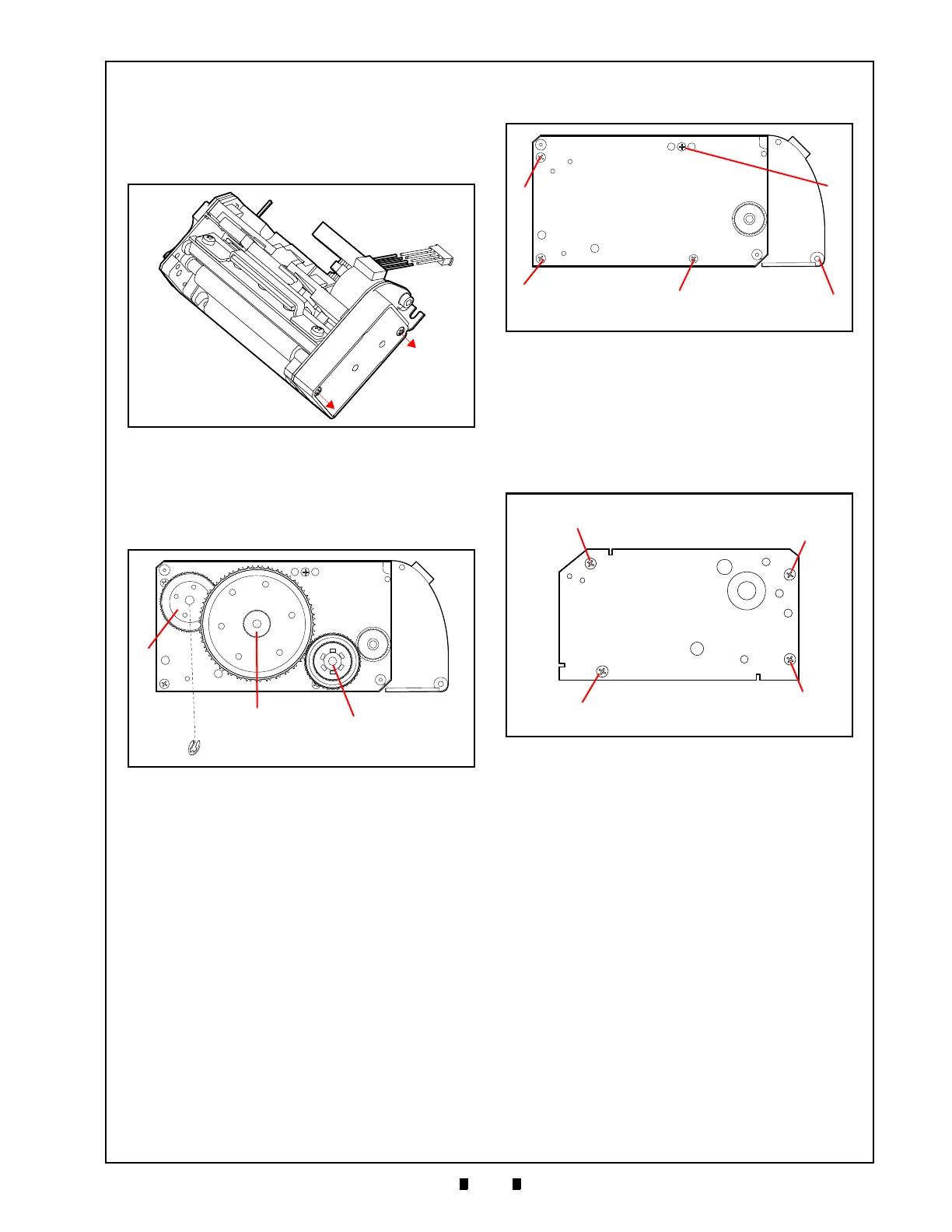
Upper Platen Roller Removal
To remove the Upper Platen Roller, proceed as
follows:
1. Remove four (4) screws that secure the Cover
(Figure 4-10 a
1
thru a
4
), then remove the Cover.
2. Remove the Platen roller.
Figure 4-7 Left Side Cover Removal
Figure 4-8 Remove Gears and E-clip
Figure 4-9 Remove Screws and Motor
Figure 4-10 Upper Platen Roller Cover
 Loading...