P/N 960-100940R_Rev. A © 2016, JCM American Corporation
Installation GEN5™ Series Printer Section 2
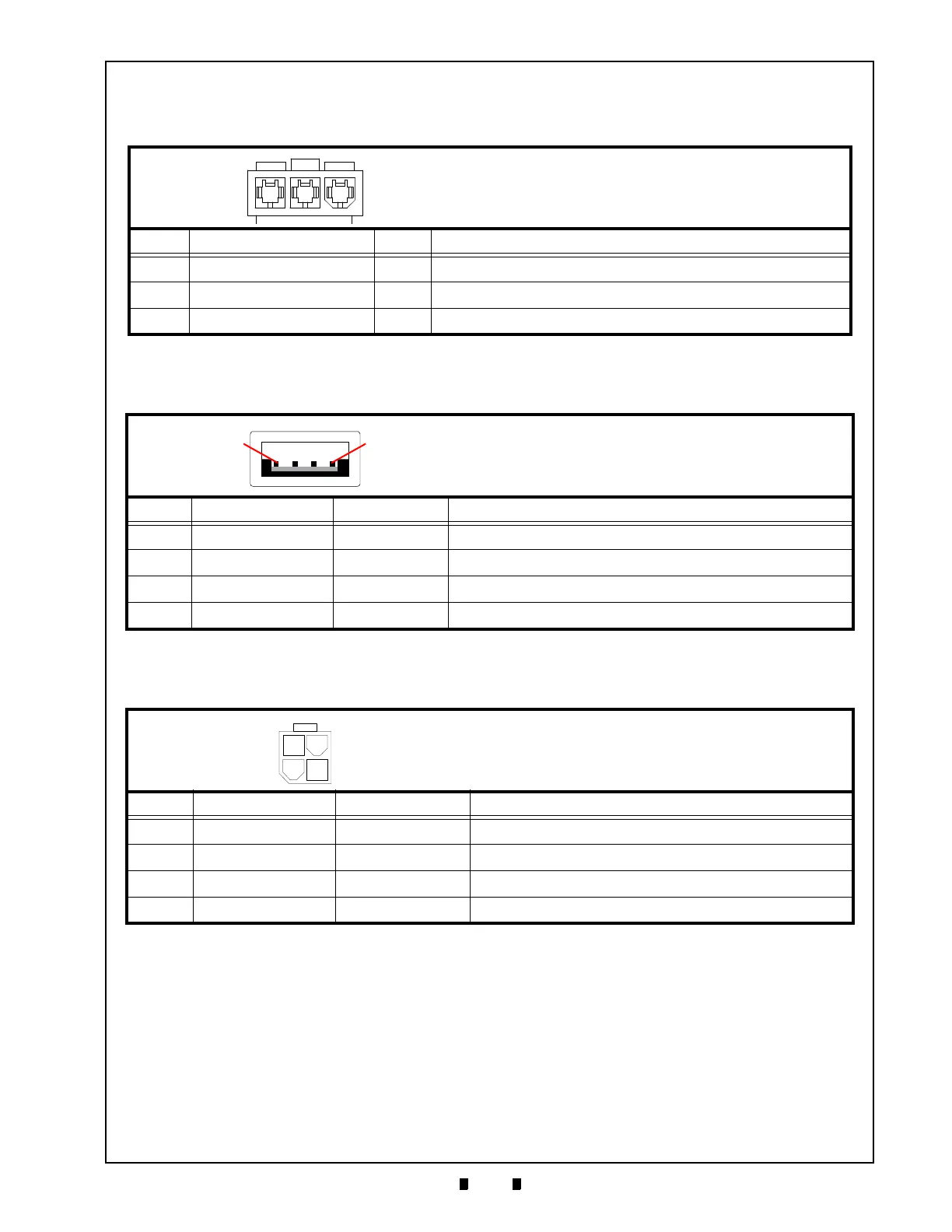
Bezel Connector (on Coil Harness) Pin Assignments
Table 2-6 lists the GEN5 Bezel Connector (on the Coil Harness) Pin Assignments.
USB Connector Pin Assignments
Table 2-7 lists the GEN5 USB Connector Pin Assignments.
Auxiliary Port Connector Pin Assignments
Table 2-8 lists the GEN5 Auxiliary Port Connector Pin Assignments.
Table 2-6 GEN5 Bezel Coil Harness Connector Pin Assignments
Pin No. Signal Name I/O Function
1 Power 24V O Switched 24V
2
No Connection
3
DGND
-
Ground
Table 2-7 GEN5 USB Connector Pin Assignments
Pin No. Signal Name I/O Function
1 VBUS - USB+5V
2 USB– I/O USB– (N)
3 USB+ I/O USB+ (P)
4 DGND - GROUND
Table 2-8 GEN5 Auxiliary Port Connector Pin Assignments
Pin No. Signal Name I/O Function
1DGND
-
GROUND
2 RX2 I RX2 232C
3 TX2 O TX2 232C
4
--
No Connection
Connector: 39-01-4037 Mini-Fit Jr. (MOLEX)
Mate: 39-01-4031 Mini-Fit Jr. (MOLEX)
Power Source: USB Connector
Connector: Coil Interface USB (Male A Connector)
USB Coil Interface Connector (2nd Port Harness)
Connector: 39-01-3042 Mini-Fit Jr. (MOLEX)
 Loading...