P/N 960-100940R_Rev. A © 2016, JCM American Corporation
Section 4 GEN5™ Series Printer Disassembly/Reassembly
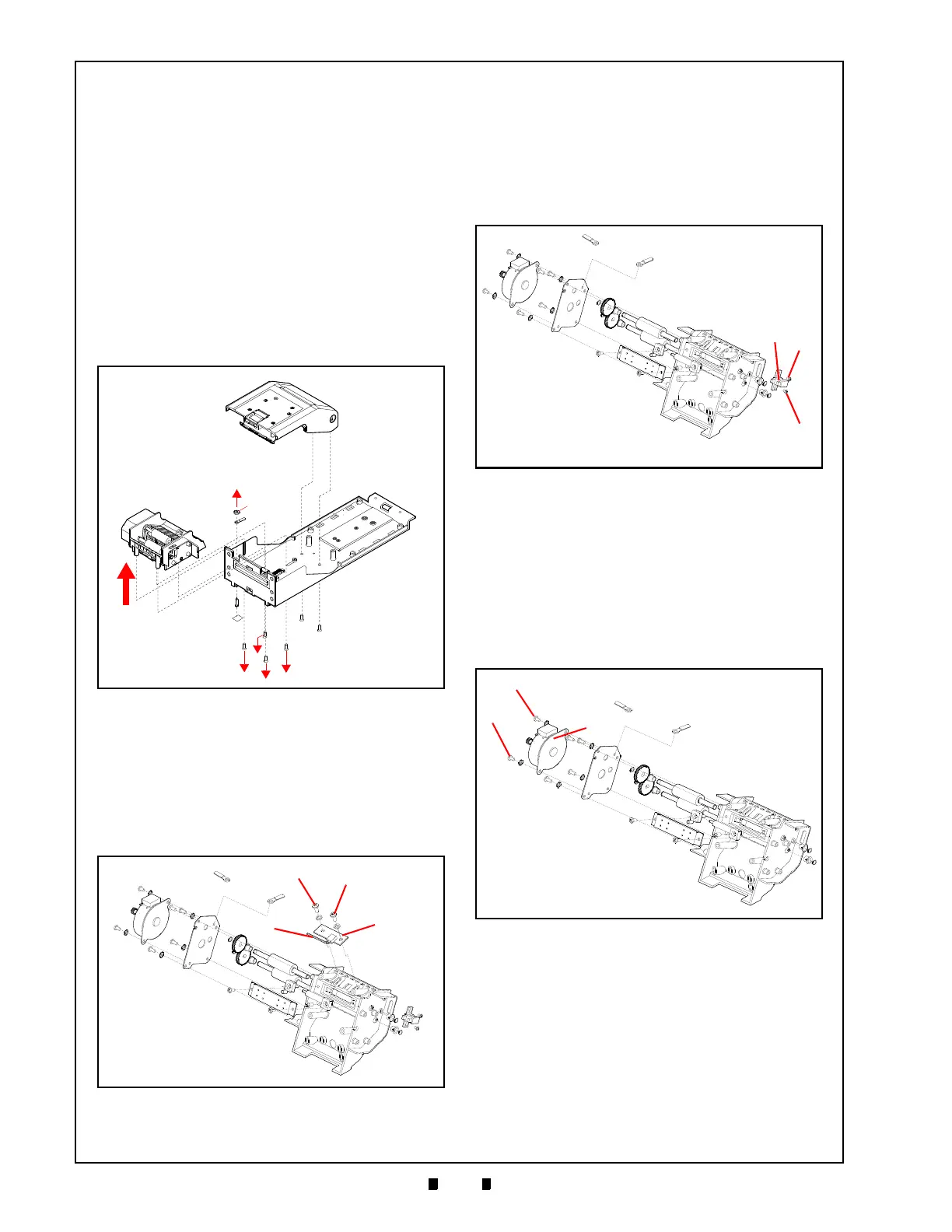
Bottom Presenter Mechanism
Disassembly
To remove the Bottom Presenter Mechanism, pro-
ceed as follows:
1. Remove four (4) screws on the bottom rails (Fig-
ure 4-11 a
1
thru a
4
).
2. Lift the Bottom Presenter upward slightly.
3. Remove the nut from the ground lug (Figure 4-11
b) u
sing a
1
⁄
4
” Nut Driver.
4. Remove two (2) screws securing the Bezel LED
Connector.
5.
Remove the Bezel LED Harness from the hold-
ing clip.
6. Lift the Bottom Presenter (Figure 4-11 c) out of
the Bottom Tray.
Taken Sensor Removal
To remove the Taken Sensor, proceed as follows:
1. Remove two (2) screws (Figure 4-12 a
1
and a
2
)
securing the Taken Sensor (Figure 4-12 b).
2. Remove one (1) connector (Figure 4-12 c).
3. Lift the Taken Sensor off the Bottom Presenter.
Lid Closed Sensor Removal
To remove the Lid Closed Sensor, proceed as fol-
lows:
1. Remove two (2) screws securing the Lid Sensor
(Figure 4-13 a
1
and a
2
).
2. Disconnect one (1) connector.
3. Remove the Lid Sensor (Figure 4-13 b).
Presenter Motor and Rollers
To remove the Presenter Motor and Rollers, pro-
ceed as follows:
Presenter Motor
1. Remove two (2) screws securing the Presenter
Motor (Figure 4-14 a
1
and a
2
).
2. Remove the Presenter Motor (Figure 4-14 b)
from the Assembly.
Figure 4-11 Remove Bottom Presenter
Figure 4-12 Remove Taken Sensor
Figure 4-13 Remove Lid Sensor
Figure 4-14 Remove Presenter Motor
 Loading...