(Main Parts)
MAINTENANCE
4-76
SM-18006
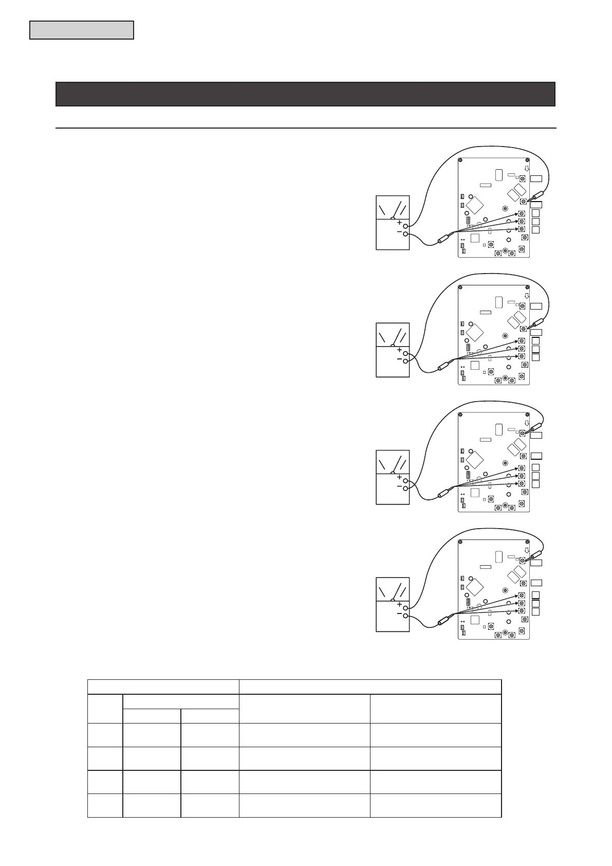
(a) By touching the + side of the tester to the P1
terminal of the inverter PCB and the - side
of tester to U, V, and W of the inverter PCB,
measure the resistance.
(b) By touching the - side of the tester to the P1
terminal of the inverter PCB and the + side
of tester to U, V, and W of the inverter PCB,
measure the resistance.
(c) By touching the - side of the tester to the N1
terminal of the inverter PCB and the + side
of tester to U, V, and W of the inverter PCB,
measure the resistance.
(d) By touching the + side of the tester to the N1
terminal of the inverter PCB and the - side
of tester to U, V, and W of the inverter PCB,
measure the resistance.
If procedures (a) to (d) are performed and the results are satisfactory, the CIB on the inverter PCB is normal.
Recommended using an analog tester.
Measurement Point Criterion
Item
Tester
Analog Tester Digital Tester
(+) (-)
(a) P1 U/V/W
1k
Ω or more
(Measured Range: 1kΩ)
Over Load
(b) U/V/W P1
100k
Ω or more
(Measured Range: 10kΩ)
1.0V or less
(c) U/V/W N1
1k
Ω or more
(Measured Range: 1kΩ)
Over Load
(d) N1 U/V/W
100k
Ω or more
(Measured Range: 10kΩ)
1.0V or less
W
V
U
P1
N1
W
V
U
P1
N1
W
V
U
P1
N1
W
V
U
P1
N1



 To Next Page