(Main Parts)
MAINTENANCE
SM-18006
4-77
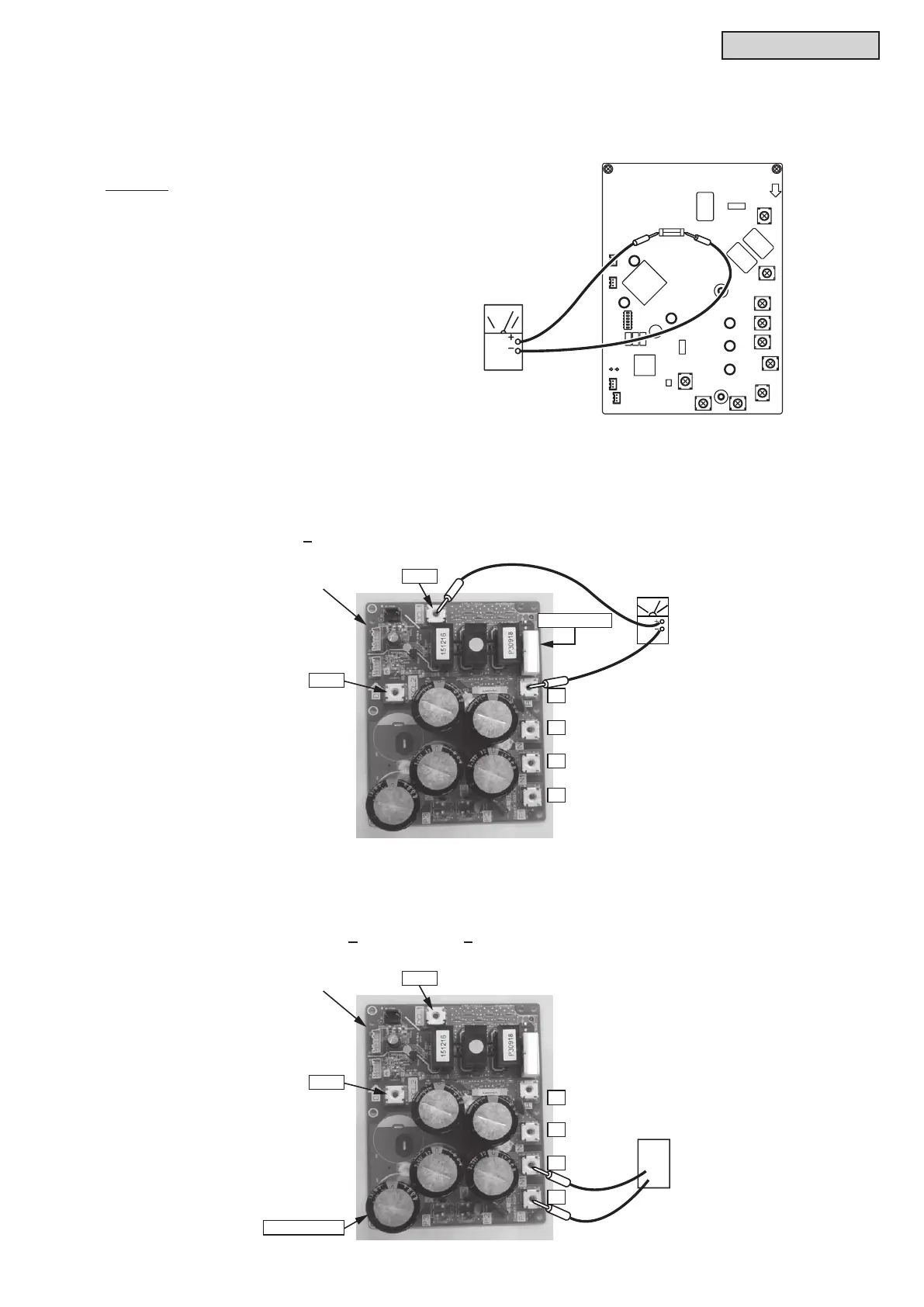
(3) Testing the Fuse for Inverter Power
By touching the + and - side of the tester on each side of the fuse (F601), measure the resistance.
If the resistance is 0Ω, it is normal.
NOTICE:
Set analog, or digital tester at 1kΩ.
There are the capacitor and resistor on MPB.
(1) Testing the Resistor
Measure the resistance using the tester between the P1 and DCL1 terminal of MPB.
If the resistance is 500Ω+5%, it is normal. (0Ω or ∞Ω: abnormal)
(2) Testing the Capacitor
(a) Check that the capacitor does not show signs of burns or isn’t swollen.
(b) Measure the capacitance using the capacitance meter between the P1 and N1 terminal of MPB.
If the capacitance is 3250
m
F+10% or 3900
m
F+10%, it is normal.
● Testing the Main Power PCB (MPB: PV153)
Tester
DCL2
B
(MPB)
DCL1
P
N1
N
P1
Resistor (RS)
F601
Capacitanc
Meter
DCL2
(MPB)
Capacitor (CB)
DCL1
P
N1
N
P1



 To Next Page