SM-18006
3-5
TROUBLESHOOTING
Install a multi-pole main switch with a space of 1/8 inch (3.5mm) or more between each phase.
Do not connect the ground wiring to gas piping, water piping, or a lighting conductor.
Gas Piping: An explosion and ignition may occur if there is escaping gas.
Water Piping: There is no effective electrical ground provided when hard vinyl piping is used.
Lightning Conductor: The electrical potential of the earth increases when a lightening conductor
is used.
● Adjust wiring size when wiring runs are abnormally long.
Electrical code must be followed and total voltage drop must not exceed 2%.
● Power supply voltage should be as follow.
Supply Voltage: Rated Voltage within +10%
Starting Voltage: Rated Voltage within -15%
Operating Voltage: Rated Voltage within +10%
Imbalance between Phases: within 3%
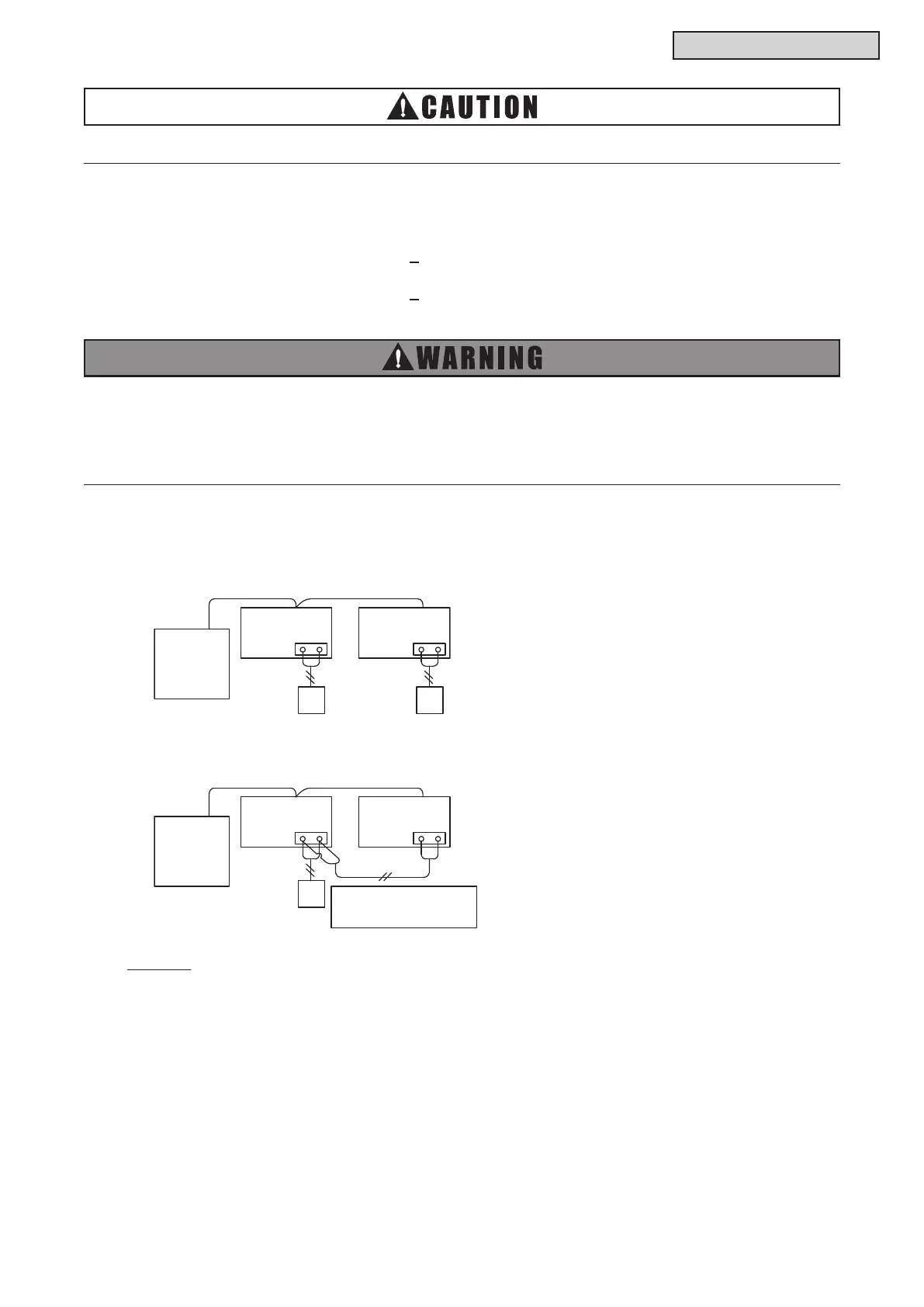
● Wired Controller Connecting Diagram
(a) Wired Controllers to each Unit for Individual Operation Setting
(b) One Wired Controller for Individual Operation Setting
Indoor Unit Indoor Unit
A B
Water Source
Unit
A B
Wired
Wired
Indoor Unit
A B
The communication cabling
for the wired controller is
necessary.
Indoor Unit
A B
Wired
Controller
Water Source
Unit
NOTICE:
Thermo-ON: The water source unit and some indoor units are running.
Thermo-OFF: The water source unit and some indoor units stay on, but don’t run.



 To Next Page