SM-18006
3-7
TROUBLESHOOTING
SEG1
SEG2
3
LED5
DSW
DSW
DSW
DSW
DSW
DSW
RSW
DSW
LED2
LED1
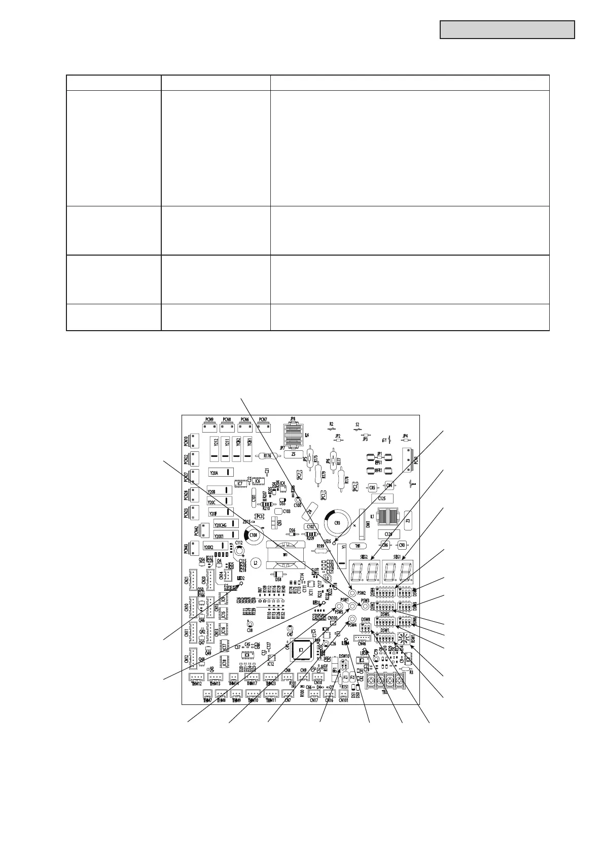
a. Control Printed Circuit Board: PCB1 (Water Source Unit PCB)
z
Purpose
Symbol PCB Purpose
PCB1 Water Source Unit PCB 1. Transmitting between Indoor Unit and Water Source Unit
2. Processing for Sensor Input
3. Processing for DIP Switch Input
4. Operation Control for Above Items 1 to 3.
Compressor Operation Control, Bypass Valve Control,
Fan Control and Overcurrent Control
5. 7-Segment Indication
6. Processing of Safety Device Input
7. Processing of Relay Output
8. Reverse Phase Detection for Power Supply
INV1, 2
(For 208/230V Type)
Inverter PCB 1. Inverter components are driven by water source unit PCB to
drive compressor.
2. Overcurrent Control
3. Protection Control for Inverter Part
INV1, 2
(For 460V Type)
Inverter PCB 1. Inverter components are driven by water source unit PCB to
drive compressor.
2. Overcurrent Control
3. Protection Control for Inverter Part
MPB1, 2
(For 208/230V Type)
Main Power PCB
1. Inverter components are driven by water source unit PCB to
drive compressor.
Further explanation of this diagram can be found on the next page.



 To Next Page