3-8
SM-18006
TROUBLESHOOTING
Part Name Function Information
LEDs
LED1 (Red)
Power Supply Indicator for Water Source Unit PCB (Low Voltage)
Normal Condition: Activated / ON
Abnormal Condition: Deactivated / OFF
LED2 (Green)
This LED2 indicates the communication state between the water source unit
PCB and inverter PCB.
Normal Condition: Flashing
Abnormal Condition: Activated / ON or Deactivated / OFF
LED3 (Yellow)
This LED3 indicates the communication state between the indoor unit and
water source unit.
Normal Condition: Flashing
Abnormal Condition: Activated / ON or Deactivated / OFF
LED4 (Orange)
This LED4 indicates the communication state between the water source units.
Normal Condition: Flashing
Abnormal Condition: Activated / ON or Deactivated / OFF
LED5 (Red)
Power Supply Indicator for Water Source Unit PCB (High Voltage)
Normal Condition: Activated / ON
Abnormal Condition: Deactivated / OFF
SEGs SEG1, SEG2
These indicate: “Alarm”, “Protective Safety Device has Tripped” or “Checking
Items”.
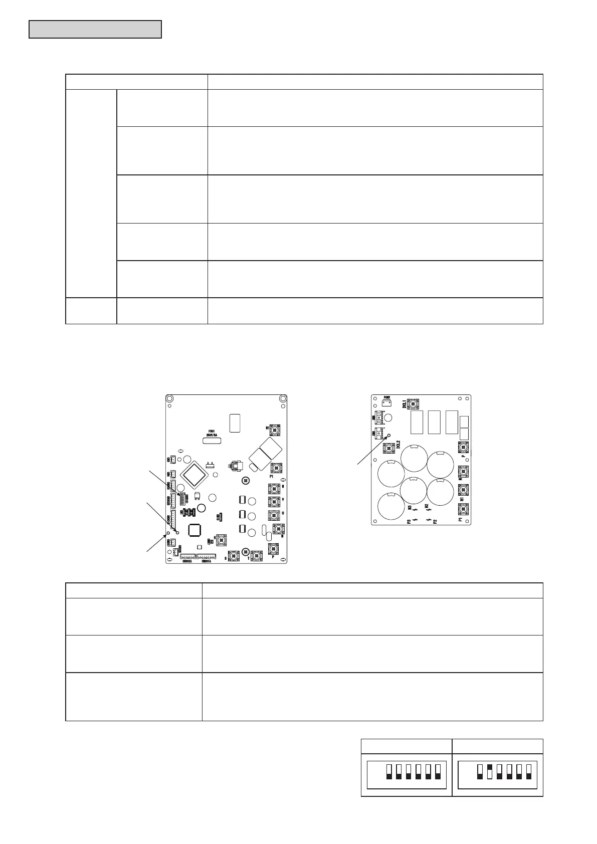
b. Inverter Printed Circuit Board for 208/230V Type: INV1, 2 (Inverter PCB) and
MPB1, 2 (Main Power PCB)
DSW101
PV151 (INV1,2) PV153 (MPB1,2)
LED202
LED203
LED501
Part Name Function Information
LED501 (Red)
(on MPB1, 2)
Power Supply Indicator for Inverter PCB
Normal Condition: Activated / ON
Abnormal Condition: Deactivated / OFF
LED202 (Yellow)
(on INV1, 2)
This indicates the state of the microcomputer.
Normal Condition: Activated / ON
Abnormal Condition: Deactivated / OFF
LED203 (Green)
(on INV1, 2)
This indicates the state of communication between inverter PCB and fan
controller. (Not Used)
Normal Condition: Activated / ON
Abnormal Condition: Deactivated / OFF
INV1 INV2
123
ON
OFF
456
123
ON
OFF
456
• DSW101
No setting is required.
When setting the No.1 pin to ON, the electric current
detection is canceled.
The No.1 pin should be set back to OFF after electrical
work.



 To Next Page