SM-18006
3-71
TROUBLESHOOTING
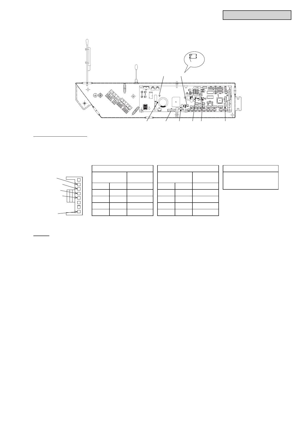
LED5 PC4
CN1 VCC15 GND VCC05 VCC13
PC4-No.2
2 FG (Blue)
3 Vsp (Yellow)
4 Vcc (White)
5 GND (Black)
8 Vdc (Red)
Checking for Fan Motor
Remove fan motor connector and measure the resistance value between each of the pins (twice, one
measurementwith+/-leadsandtheotherwith-/+leads).Checkwhethertheresistancevalueisoveror
not according to the table shown below. When performing the second measuring, make sure to switch
leads(Red/Black).
1st 2nd Decision Basis
Tester
Resistance
Value
Tester
Resistance
Value
Resistance values
of both 1st and 2nd
measurings are over 10
Red Black
W
Red Black
W
FG GND GND FG
Vsp GND GND Vsp
Vcc GND GND Vcc
Vdc GND GND Vdc
●Exampleof4-WayCassetteType
NOTE:
For details, refer to “Service Manual for Indoor Unit”.



 To Next Page