3-72
SM-18006
TROUBLESHOOTING
l
TheRUNindicator(red)ashes.
l
The indoor unit number (refrigerant cycle number - address number), the alarm code, the model code
1
,
the model name
1
and the number of connected indoor units are displayed on the LCD. The indoor unit
number and the alarm code are displayed on the 7-segment display of the water source unit PCB.
Note 1: Except for some models.
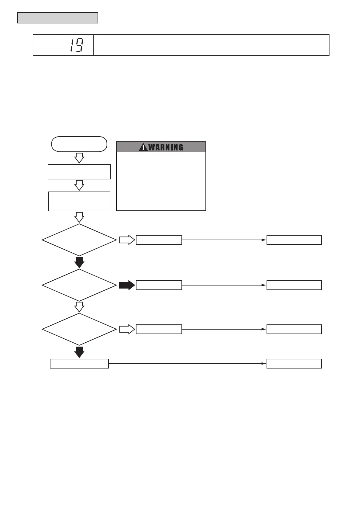
Thisalarmcodeisdisplayedwhentheindoorfanmotorrotatesatlessthan70rpmforvesecondsthree
times in 30 minutes during the operation.
Failure of I.U. PCB2
Failure of Fan Motor
Failure of I.U. PCB2
1: Abnormal voltage is supplied
for fan motor.
Is LED1 on
I.U. PCB2 OFF?
1
Check connectors PCN201
and CN201 on I.U. PCB2.
No
No
Yes
Does fan motor run?
Replace I.U. PCB2.
Replace Fan Motor.
Replace I.U. PCB2.
Replace Fan Motor
Yes
Yes
Occurrence of
Alarm Code “19”
(Normal Voltage: DC 280V)
Failure of Fan Motor
No
Check that 208/230V
is applied between
L1 and L2 of TB1.
Dose fan motor
meet decision basis
at “Checking for
Fan Motor”?
● Perform the following check after
setting the airflow volume to “HIGH”.
● High voltage is applied to electrical
parts. Perform the check carefully to
prevent an electrical shock.
● Turn OFF the power supply completely
before checking connector. Otherwise,
it may cause a DC fan motor failure.
(Built-in PCB for the DC fan motor may
be damaged.)
Alarm
Code
Activation of Protection Device for Indoor Fan Motor
(Ducted (Medium Static and Slim) Type)



 To Next Page