JOHNSON CONTROLS
165
SECTION 6 – USER INTERFACE CONTROL CENTER
FORM 145.05-NOM7
ISSUE DATE: 10/31/2019
6
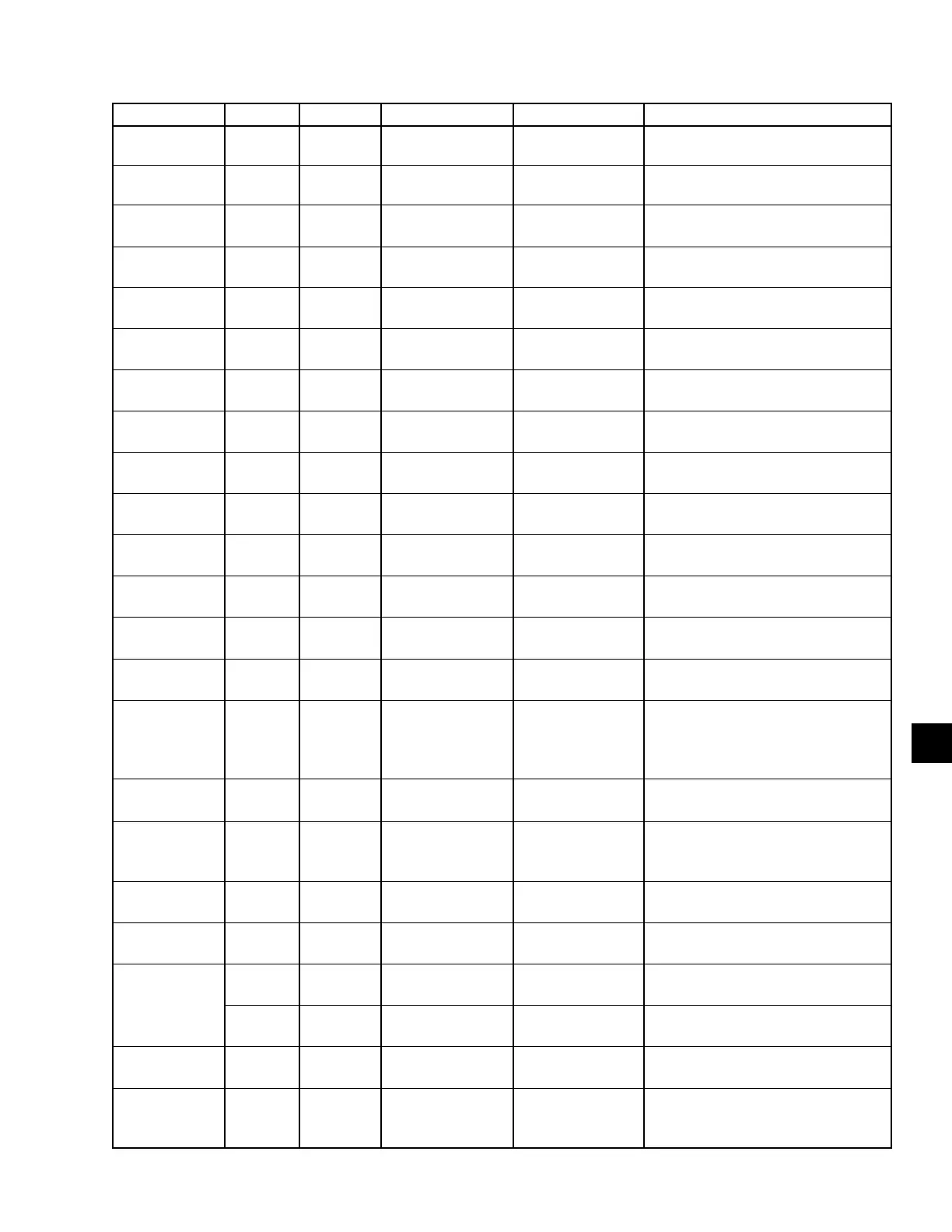
DISPLAY TEXT TYPE ID VALUE RANGE LOCATION DESCRIPTION
Supply Fan
Status
Digital
Input
J13-2 Running / Stopped I/O Board
Digital Input for the Supply Fan Run
Verication Circuit
Water Flow
Switch
Digital
Input
J13-10 On / Off I/O Board
Digital Input from the Water Flow
Switch
Compressor A
Digital
Output
J16-1 On / Off I/O Board
Status of the Digital Output to Com-
pressor A
Compressor A
Load
Digital
Output
J12-2 1-5Vdc I/O Board
Analog Output to the Digital Com-
pressor Controller
Compressor B
Digital
Output
J16-2 On / Off I/O Board
Status of the Digital Output to Com-
pressor B
Compressor C
Digital
Output
J16-3 On / Off I/O Board
Status of the Digital Output to Com-
pressor C
Compressor D
Digital
Output
J16-4 On / Off I/O Board
Status of the Digital Output to Com-
pressor D
Compressor E
Digital
Output
J16-5 On / Off I/O Board
Status of the Digital Output to Com-
pressor
Compressor F
Digital
Output
J16-6 On / Off I/O Board
Status of the Digital Output to Com-
pressor F
Electric Heat
Stg 1
Digital
Output
J31-1 On / Off I/O Board
Status of Electric Heat Digital Output
To Stage 1
Electric Heat
Stg 2
Digital
Output
J31-2 On / Off I/O Board
Status of Electric Heat Digital Output
to Stage 2
Electric Heat
Stg 3
Digital
Output
J31-3 On / Off I/O Board
Status of Electric Heat Digital Output
to Stage 3
Electric Heat
Stg 4
Digital
Output
J31-4 On / Off I/O Board
Status of Electric Heat Digital Output
to Stage 4
OCC/UNOC
Indication
Digital
Output
Tb1-9, 10 On / Off I/O Board
Gives the Occupied / Unoccupied
Status
Pump Start
or Isolation
Damper
Digital
Output
User Enabled/Dis-
abled
Tb1-11, 12
These functions cannot be combined.
One or the other can be used, and
the description of their operation can
be found in Table 43 on page 183
Supply Fan
Output (CV)
Digital
Output
J17-5 On / Off I/O Board
Status of Supply Fan Digital Output
for Constant Volume
Supply Fan
Output (VAV,
FLEX)
Digital
Output
J17-3 & 4 On / Off I/O Board
Status of Supply Fan Digital Output
For VAV or Flex
Supply Fan VFD
Bypass Relay
Digital
Output
Tb17-6 On / Off I/O Board
Digital Output is Turned On when Set
to Bypass
VAV Heat
Relay
Digital
Output
Tb1-12 On / Off I/O Board
Status of the Digital Output for the
VAV Heat Relay
Data Log Error
Error
Detail
See Table 51
Data Log Error Detail
(Only Displayed when Error is Present)
Error
State
See Table 50
Data Log Error State
(Only Displayed when Error is Present)
Data Log
Format
Off
Used to Activate the Data Log Fea-
ture of the Control
DE Modifier
Address
-1 to 41943
Used to Enter a Specic DE Instance.
See SECTION 6 – USER INTER-
FACE CONTROL CENTER
TABLE 40 - SERVICE (CONT'D)
 Loading...


