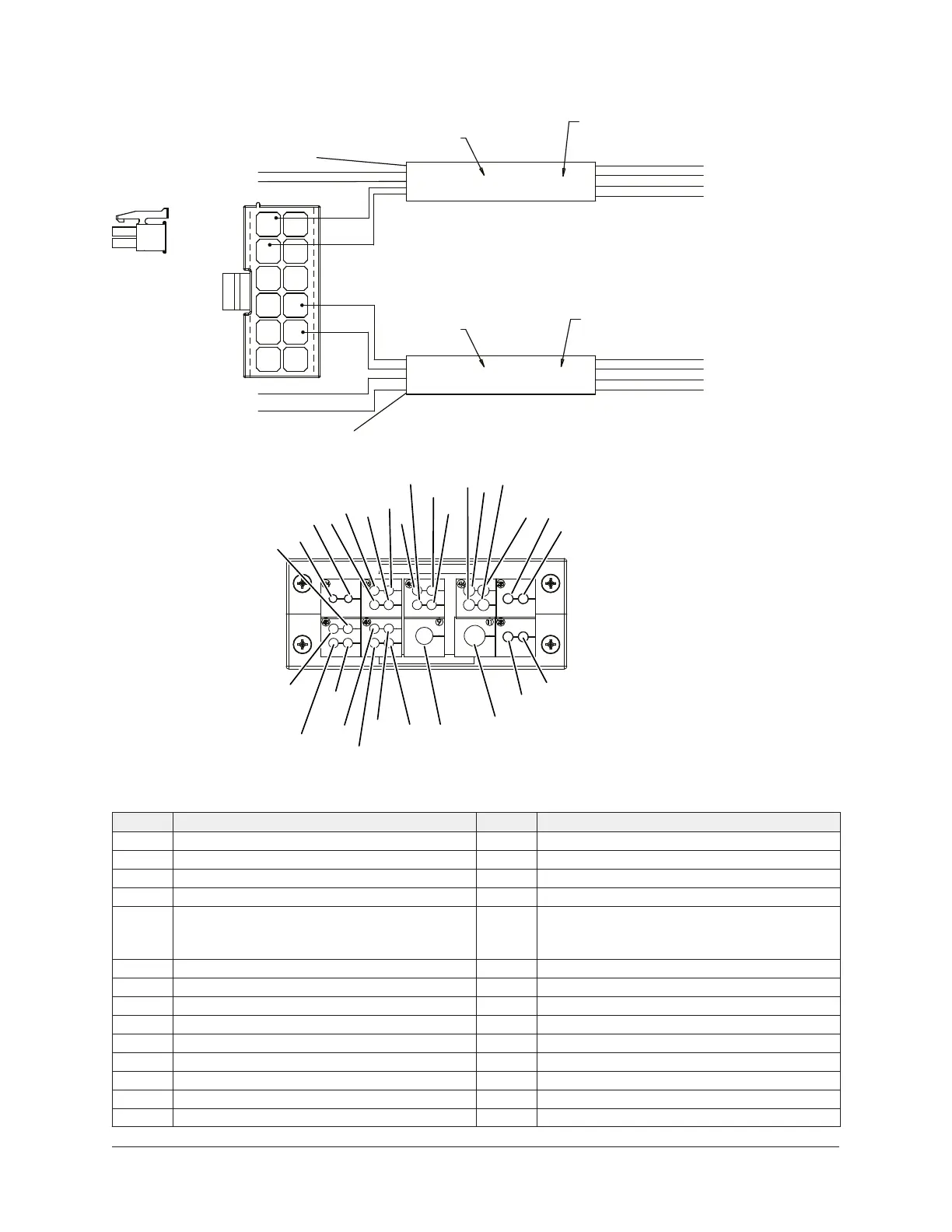
Figure 37: OptiView cable entry and flow switch details
092-62925-000
REV B, SHT.2
P14 INCLUDED AS PART
OF SHIELDED CABLE ASM.
Optional Evaporator Flow Switch (EFS) and Condenser Flow Switch (CFS) Internal Optiview P14 Pinout View
Shielded Cable Entry View From Outside of Panel
Item Description Item Description
1 Cable 12 (Cond. Pressure) 15 Cable 6 (Drop Leg Refrigerant Temp.)
2 Cable 1 (Leaving Chilled Water) 16 Cable 32 (VGD COMM/POS. Feedback)
3 Cable 5 (Return Cond. Water Temp.) 17 Cable 19 (MBC)
4 Cable 4 (Leaving Cond. Water Temp.) 18 Cable 23 (OVA)
5 Cable 9 (Return Chilled Water Temp.) 19
Cable 22 (Optional HGBP Actuator) Remove
Grommet Plug And Insert Cable, (Item 2) From
HGBP Kit Sales Order.
6 Cable 39 (HPCO Switch) 20 (Evap. Water Flow Switch)
7 Cable 51 (Purge Tank High Level Switch) 21 (Cond. Water Flow Switch)
8 Cable 29 (Motor Housing Temp.) 22 Cable 33 (Motor Cooling Valve)
9 Cable 48 (Cond. Refrigerant Temp.) 23 No Cable
10 Cable 49 (Purge Coil Temp.) 24 No Cable
11 Cable 50 (Purge Suction Temp.) 25 No Cable
12 Cable 52 (OV Fault To VSD) 26 Cable 24 (Discharge Pressure)
13 Cable 7 (Evap. Refrigerant Temp.) 27 Cable 11 (Evap. Pressure)
14 Cable 2 (Discharge Temp.) 28 Cable 15 (Refrigerant Level)
63Unit Wiring and Field Connections for YZ Centrifugal Chiller with Magnetic Bearing Controller