EasyManua.ls Logo

Johnson Controls YZ - Page 66

Johnson Controls YZ
94 pages
Print Icon
To Next Page IconTo Next Page
To Previous Page IconTo Previous Page
Loading...
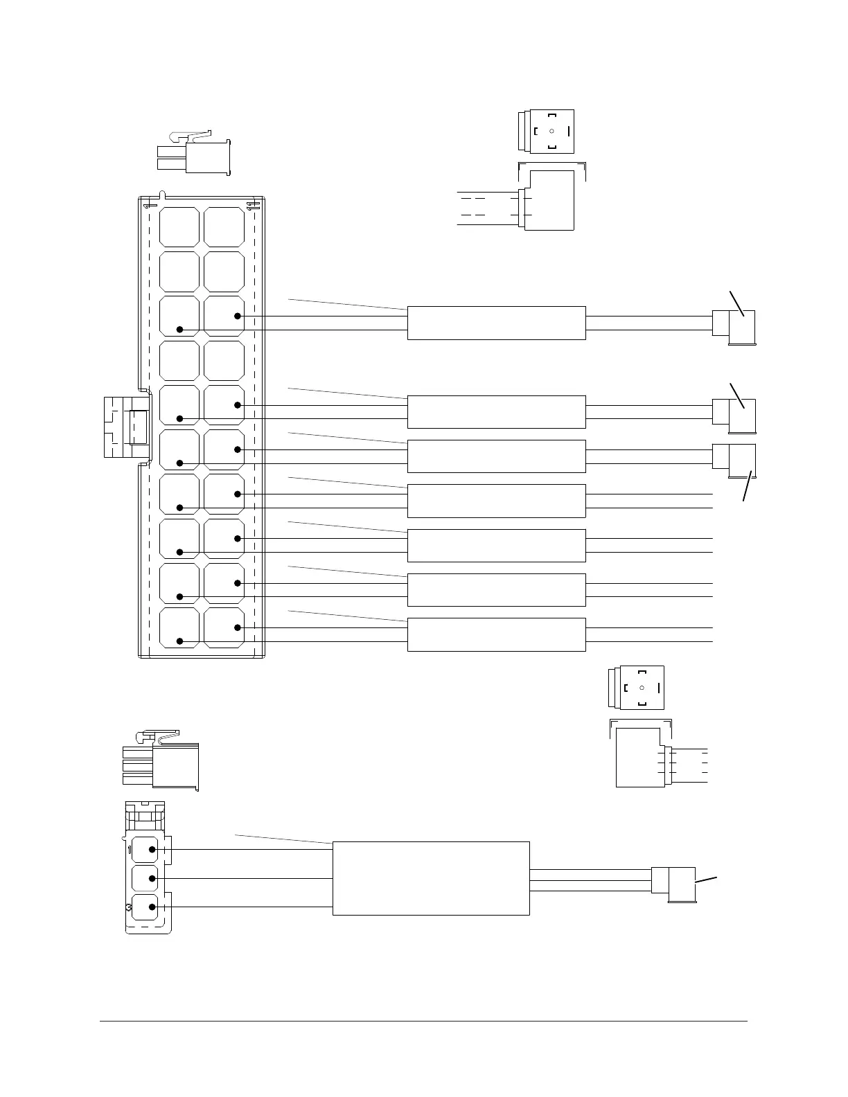
Figure 40: OptiView connections for cables 1, 2, 4, 5, 6, 7, 9, and 24
LD23069
11
20
2
3
13
4
14
5
15
6
16
7
17
8
18
9
19
1
10
12
2
3
1
1
2
3
2
3
1
RED
BLK
BLK
BLK
BLK
BLK
BLK
BLK
RED
RED
RED
RED
RED
RED
P9
Cable 7: Evap. Refrigerant
Temp.
Cable 2: Discharge Temp.
Cable 6: Drop Leg Refrigerant
Temp.
Cable 5: Return Condenser
Water Temp.
Cable 4: Leaving Condenser
Water Temp.
Cable 9: Return Chilled Water
Temp.
Cable 1: Leaving Chilled
Water
RED
BLK
RED
RED
RED
RED
RED
RED
DRAIN
DRAIN
DRAIN
DRAIN
DRAIN
DRAIN
DRAIN
BLK
BLK
BLK
BLK
BLK
BLK
See Detail B Above
Detail B
RED
BLK
(PIN 2)
(PIN 1)
GND
WHT
WHT
DRAIN
RED
BLK
RED
BLK
P1A
Cable 24: Discharge Pressure
See
Detail D
Above
RED
BLK
WHT
(PIN 3)
(PIN 1)
(PIN 2)
GND
Detail D
092-51870-009
REV F, SHT.2, 4
See Detail B Above
See
Detail B
Above
Unit Wiring and Field Connections for YZ Centrifugal Chiller with Magnetic Bearing Controller66

Table of Contents

Related product manuals