1-8
1.5 GENERAL SYSTEM DIAGRAMS
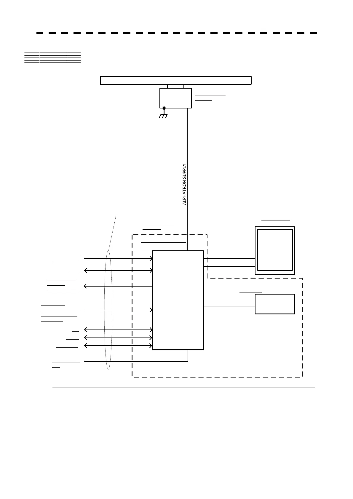
Fig. 1.4 General System Diagram of Radar, Type JMA-610
Note: Eliminating the interference on frequencies used for marine communications and navigation due to
operation of the radar.
All cables of the radar are to be run away from the cables of radio equipment.
(Ex. Radiotelephone. Communications receiver and direction finder, etc. )
Especially inter-wiring cables between scanner unit and display unit of the radar should not be run
parallel with the cables of radio equipment.
SHIP㵭S MAIN
24V
ALPHATRON SUPPLY
RADAR PROCESS UNIT
NDC-1486
CONTROL UNIT
NCM-883
JRC SUPPLY
7m
OPERATING UNIT
NCE-7882A
19inch
COLOR LCD
(SXGA)
RGB
ALPHATRON SUPPLY
DC100V
ALPHATRON SUPPLY
DISPLAY UNIT
ALPHATRON SUPPLY
SCANNER UNIT
NKE-316
RADIATOR NAX-16A-7
Alpha chart
GPSx2
NMEA (Input)
HDG /Depth
/Temperature /ROT
/Rudder /Autopilot
/Time /Trip
NMEA (output)
Cursor or
own ship㵭s data
PS/2
Analog (input)
ROT/ Rudder
AIS
 Loading...


