7.2 TROUBLE SHOOTING
yyy
yyyy
7-5
7
7.2 TROUBLE SHOOTING
As this radar equipment includes complicated circuits, it is necessary to request a specialist engineer for repair
or instructions for remedy if any circuit is defective.
There are also troubles by the following causes, which should be referred to in checking or repair work.
1 Poor Contact in Terminal Board of Inter-Unit Cables
a) Poor contact in terminal board
b) The cable end is not fully connected, that it, contacted with earthed another terminal.
c) Disconnected cable wire
2 Poor Contact of Connector within Unit
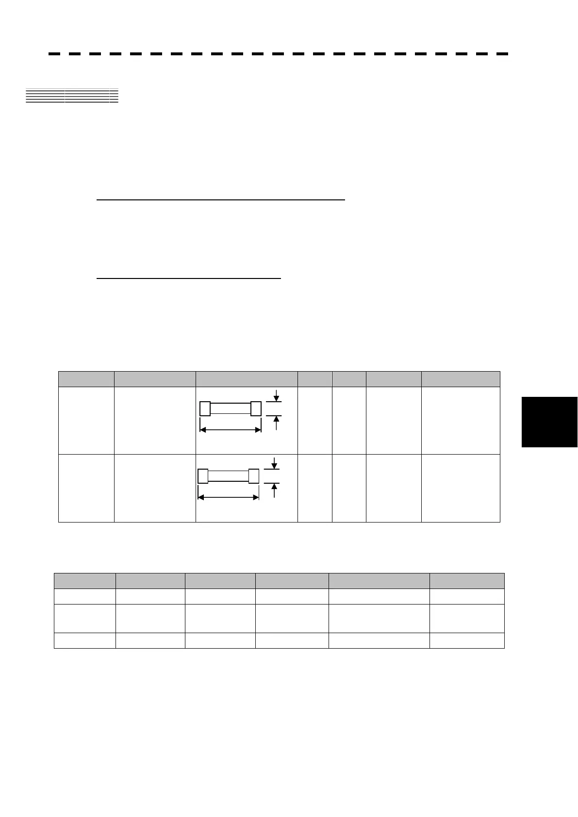
Reference: This radar equipment is provided with standard spares which include two kinds of fuses. Refer
to table 7-4.
Table 7-4 Spare Fuses ( for NCM-883)
Name Type/Code Shape (mm) In use Spare Parts No. Location
Fuse
ST4-5AN1
(5ZFCA00050)
1 3 F401
Inside processing
unit
Fuse
ST6-8AN1
(5ZFCA00052)
1 3 F402
Inside processing
unit
Table 7-5 Special Parts ( for NKE-316 )
Parts No. Name Type Manufacturer Location Code
V101 Magnetron MAF1562R New JRC Scanner 5VMAA00116
A101 Circulator FCX68R
Orient
Microwave
Scanner 5AJIX00027
A102 Diode Limiter NJS6930 New JRC Scanner 5ATBT00006
31.8
Ǟ6.35
31.8
Ǟ6.35
 Loading...


