6-14
6.2.2 Equipment Cable End Processing
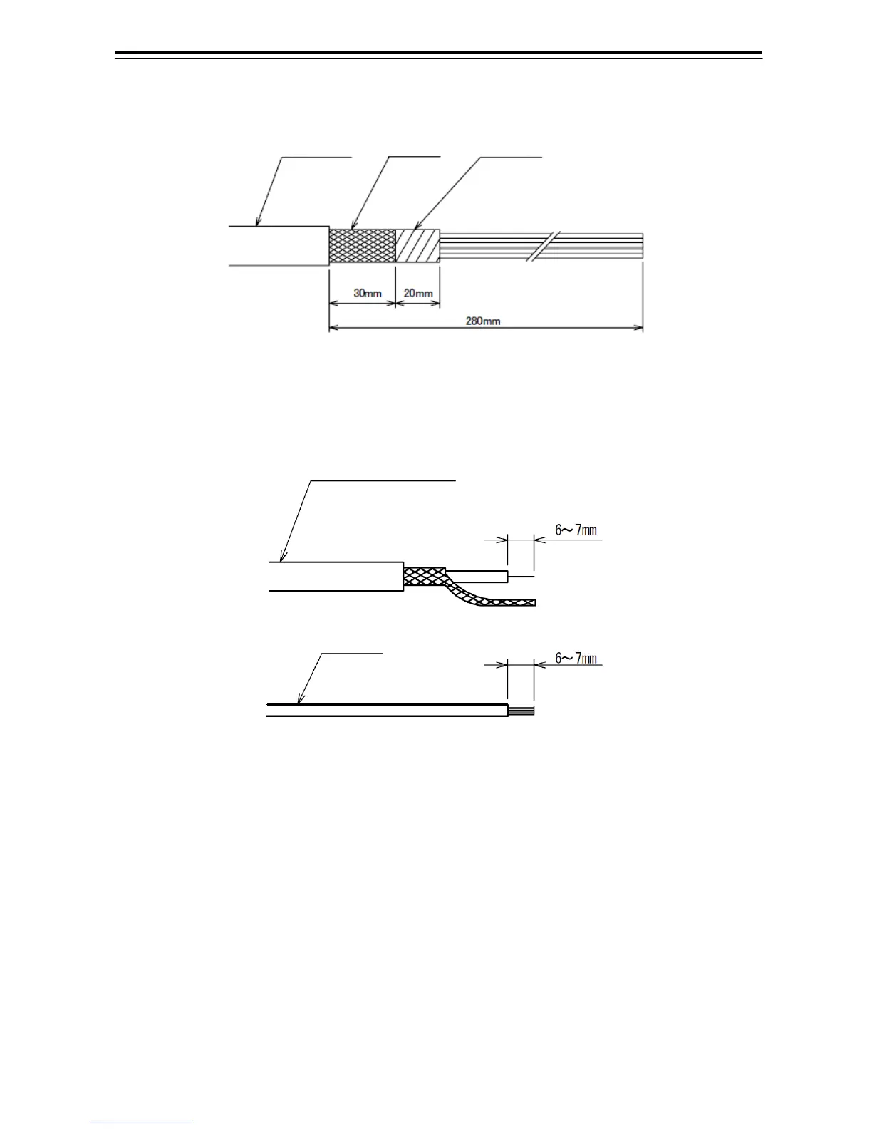
Fig 6-14: Equipment cable end processing
6.2.3 End Processing of each cable core
Fig 6-15: End processing of each cable core
6.2.4 Connection to Display Unit
Use 14-core composite cable 2695110056 and coaxial cable RG-10/UY to connect power control
unit NQE-3167 to each display unit of NCD-2096/F.
Among the two cables, use coaxial cable RG-10/UY to connect the radar video signal.
For the procedures for processing the cable end and the wiring procedures, see Fig 6-14:
Equipment cable end processing.
For the wiring procedures, see Section 6.2.6 Inter-board connection diagram of power control unit.
Coaxial or Shield cable
Vinyl cable
Shielding
Equipment cable
Tape