4-8
4.5 Setting of GYRO I/F
4.5.1 Setting of STEP・SYNC
The GYRO I/F circuit of the system accepts most GYRO compasses by switching behavior.
Step motor Type: DC24~DC100V
Synchro-motor Type: Primary excitation voltage 50V~115V(AC)
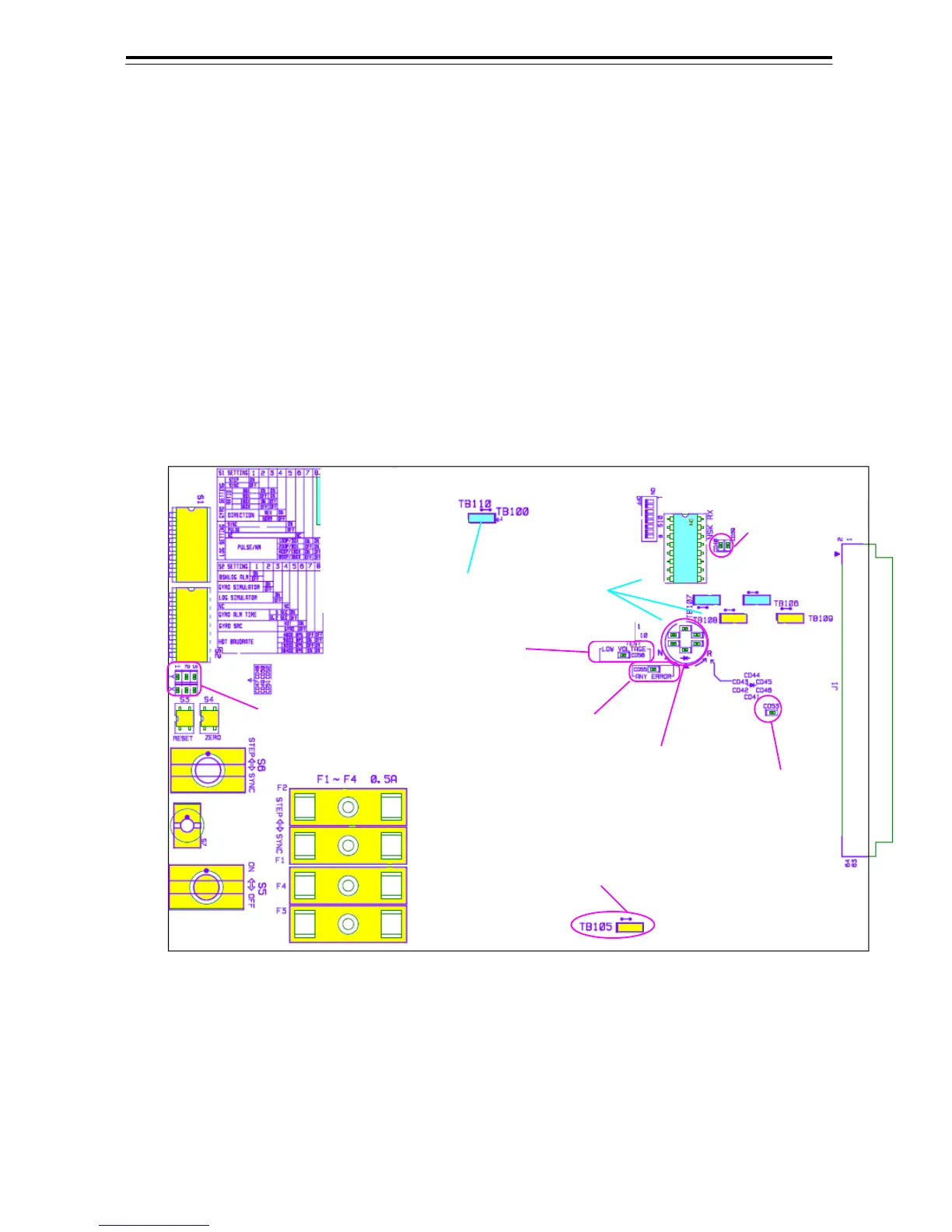
Before power-on operation, do the setting of the switches S1, S2, S5, S6, S7 and jumper JP1 on the
GYRO I/F circuit (PC-4201) for your Gyro compass type by performing the procedure below.
The switches are factory-set for a gyration ratio of 180X and the step motor type. Make sure of the
type gyro compass installed on the own ship before starting the procedure below.
GYRO I/F 回路設定箇所
Setting point on GYRO I/F circuit
GYRO INPUT SIGNAL
INDICATOR LED
ジャイロ入力信号LED
GYRO SIGNAL PROCESS
INDICATOR LED
ジャイロ信号処理表示LED
LOG PULSE
INDICATOR LED
ログパルス表示LED
ERROR INDICATOR LED
エラー表示LED
GYRO LOW-VOLTAGE
ALERT LED
ジャイロ低電圧警告LED
KEEP DEFAULT
設定不要
LOW-VOLTAGE GYRO
SETTING
ジャイロ低電圧時に設定
OPEN
プラグ無し
SERIAL SIGNAL
INDICATOR LED
シリアル信号表示LED