4-4
4.3 Setting Equipment Configuration
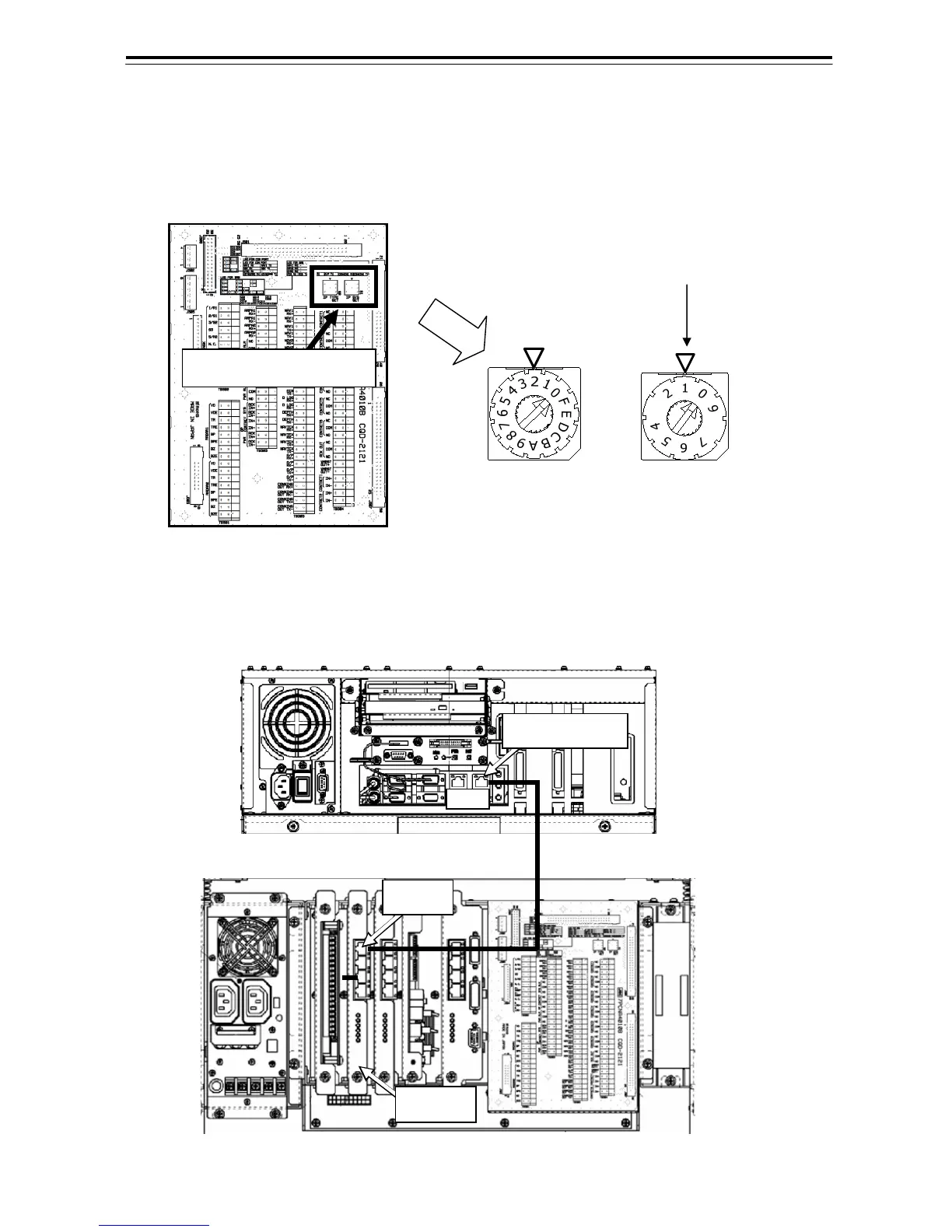
4.3.1 Setting Ethernet Rotary Switch
1) Set Ethernet Rotary Switch on the CQD-2121 Standard Terminal Board.
2) Connect between the “MAIN1” LAN in the SRB1 and the 1000 Base-LAN in the Main Control Unit.
CQD-2121 Standard Terminal Board
8
3
IP TYPE SET(S2)=2 IP SYS SET(S1)=1 to 4
Main Control Unit
LAN Cable
1000 Base-LAN
MAIN1
SRB1
Ethernet Rotary Switch
In the case with plural Display Unit, set the
number of the Display Unit so as not to overlap.