4-5
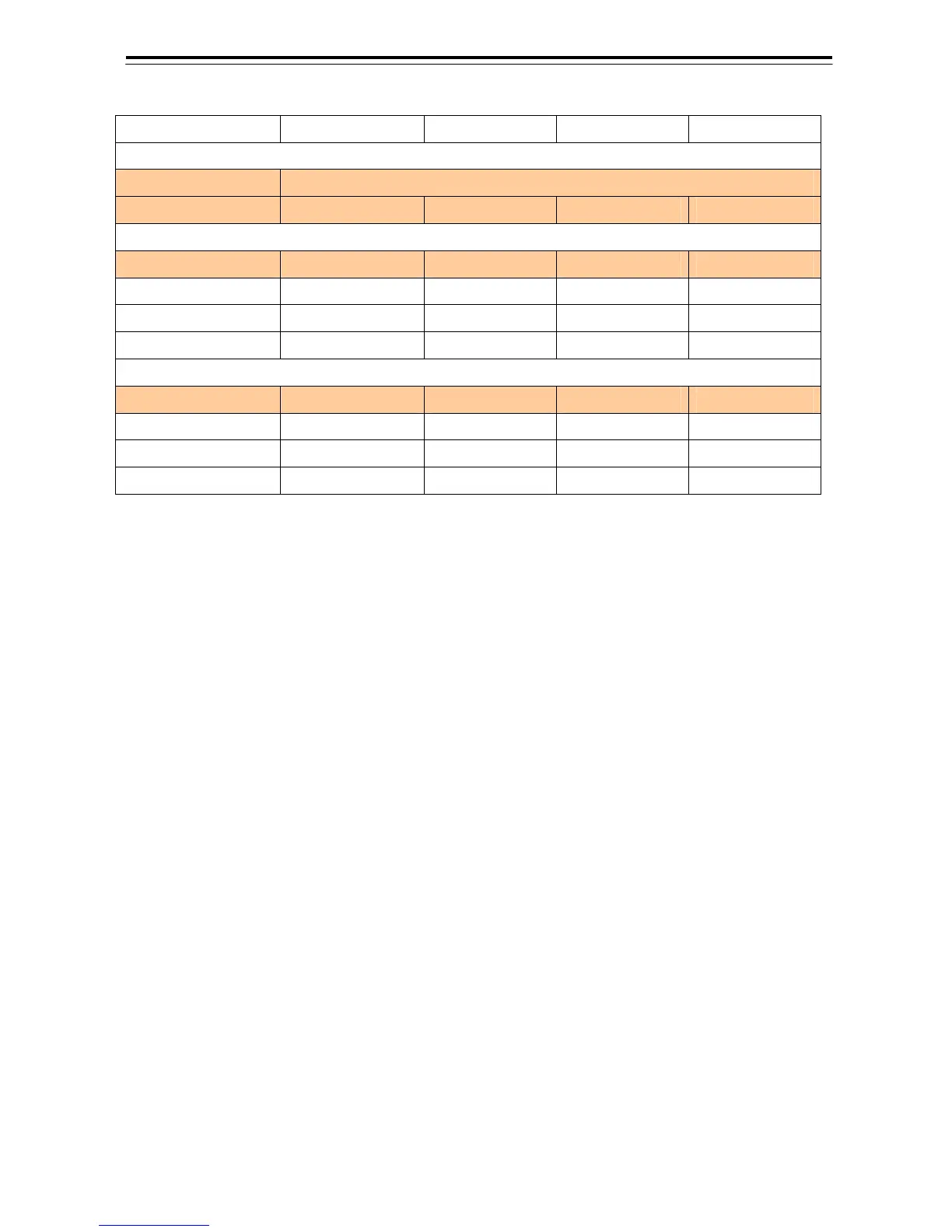
Relation between Ethernet Rotary Swtch and IP Address
Number of Display Unit No.1 Chart Radar No.2 Chart Radar No.3 Chart Radar No.4 Chart Radar
Setting of Ethernet Rotary Switch
IP TYPE (S2) 2
IP SYS (S1) 1 2 3 4
IP Address (Main)
Processing Unit 192.168.60.35 192.168.60.41 192.168.60.47 192.168.60.53
Serial Relay I/F Board1 192.168.60.36 192.168.60.42 192.168.60.48 192.168.60.54
Serial Relay I/F Board2 192.168.60.37 192.168.60.43 192.168.60.49 192.168.60.55
Radar I/F Board 192.168.60.38 1923168.60.44 192.168.60.50 192.168.60.56
IP Address (Sub)*
Processing Unit 192.168.61.35 192.168.61.41 192.168.61.47 192.168.61.53
Serial Relay I/F Board1 192.168.61.36 192.168.61.42 192.168.61.48 192.168.61.54
Serial Relay I/F Board2 192.168.61.37 192.168.61.43 192.168.61.49 192.168.61.55
Radar I/F Board 192.168.61.38 1923168.61.44 192.168.61.50 192.168.61.56
*: IP address of Sub is not used now.
Refer to “5.3.1 The Configuration Setting” for the confirmation of IP address.
IP address of Serial Relay I/F Board1, Serial Reley I/F Board2 and Radar I/F Board is decided by setting the
Ethernet rotary switch.
When IP address of Processing Unit has not paired with the Ethernet rotary switch, it is not possible to
communicate.