2-43
2) Electrical selection criteria
• The installation height of the scanner relates to the maximum detection
distance. The higher is better. However, if it is too high, radio wave energy
greatly attenuates above the scanner's vertical beam width (the point -3dB
from the peak of the main lobe). As a result, it is difficult to detect a close-in
target. Sea clutter also increases. Determine the installation height by
taking into consideration the weight, maximum length of the cable, and
maintenance after installation.
• If the installation height of the scanner is low, it is difficult to detect a long
distance target. The ship's mast, derrick, and chimney interfere with
radiating beam causing the range that cannot be viewed on the radar display
to increase.
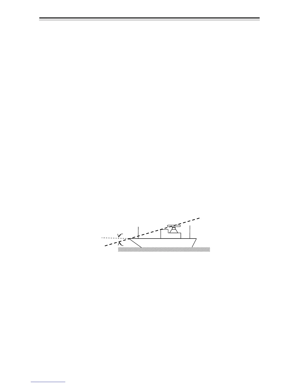
• Generally, the lowest scanner installation position is supposed to be on the
A-B line shown in Fig 2-15.
In the case of the JMA-922B/923B type radar, 2θ equals 20°.
In the case of the JMA-932B/933B type radar, 2θ equals 25°.
Specifically, the scanner position is normally elevated so that the chimney and
the shrine-gate type mast do not interfere with radiating beam.
Fig 2-12 Lowest scanner installation height
JMA-922B / 923B :θ=10°
JMA-932 B/ 933B :θ=12.5°
A
B
θ
 Loading...


