FX-1/FX-1R Maintenance Manual
13-5-2. XY-Axis Driver Indication Display
An indication display showing the status is mounted on the front of the XY-driver.
Normally, this indication shows the status as shown in the following.
#
LED表示 Ab C# D# XL軸 1
2
3
)
4
1
→→
内容
イニシャライズ中 サーボオフ サーボオン
XR軸
YBL軸
#には軸番号が表示される(右表を参照
YBR軸
YA軸
YA-axis
YBR-axis
YBL-axis
XR-axis
XL-axis
# shows an axis No. (For details, see the table on the right.)
Servo ONServo OFFDuring initialization
Contents
LED indication
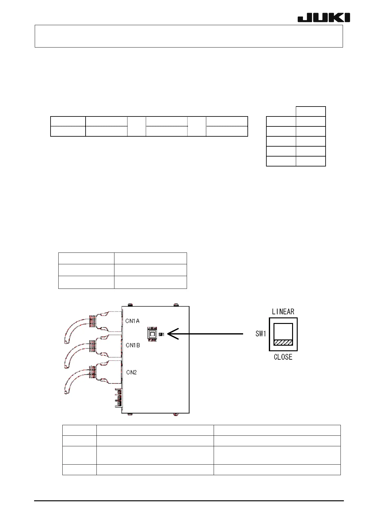
13-5-3. Scale I/F Unit
Four scale I/F units (or five scale I/F units in case of FX-1R) are mounted on the right side of the
XY-driver.
The axis names are the YBL-, YBR-, XL-, and XR-axis from the left end when viewed from the front
of the machine.
In case of FX-1R, the axis names are the YA-, YBL-, YBR-, XL-, and XR-axis.
Servo amplifier SW1 setting
XL, XR LINEAR
YBL, YBR CLOSE
* YA is for FX-1R only.
13-23
FX-1 FX-1R
CN1A Connected to the SCALE-I/F PCB. Connected to the SCALE PCB.
CN1B
Connected to the motor encoder
(YB-axis only)
Connected to the motor encoder (X-axis
is not connected).
CN2 Connected to the servo amplifier. Connected to the servo amplifier.
Rev. 2.00
 Loading...


