FX-1/FX-1R Maintenance Manual
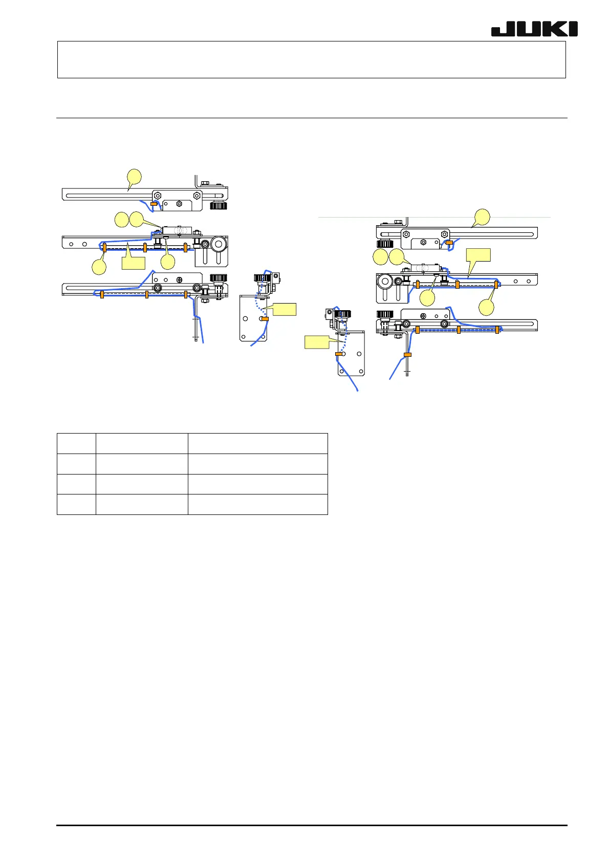
5-7. Replacing the IN and OUT Sensors
Bind the cables A and B with binding bands, taking care that they are not pulled or loosened
excessively during adjustment of sensor position.
②
③
①
②
①
④
⑤
③
A
B
Left-side sensor
⑤
④
A
B
Right-side sensor
Figure 5-7-1
d
L828E8210A0 IN SENSOR ASM
e
L832E3210A0 OUT SENSOR ASM
f
SL4031291SC SCREW
g
EA9500B0000 CABLE_BAND
<Adjusting the sensitivity>
Make an adjustment so that a (matte) black glass epoxy PWB placed on the transport path can be
detected. Place a (matte) black glass epoxy PWB under the sensor and rotate the sensitivity
adjustment knob of the sensor counterclockwise. Then gradually rotate it clockwise up to the
position at which the specified PWB is detected.
5-9
Rev. 2.00
 Loading...


