85
14 Accessories
14.1 External relay module/logic module ER8/EL8
By using the external relay module ER8 or logic module EL8, the controller can
be expanded by eight relay outputs (changeover contacts) or logic outputs (0/
12 V). Communication with the controller occurs via the RS422/485 interface.
All controller signals for switching outputs can be output by the module.
Configuration is only possible through the setup program.
v Section 7.4 “Outputs”
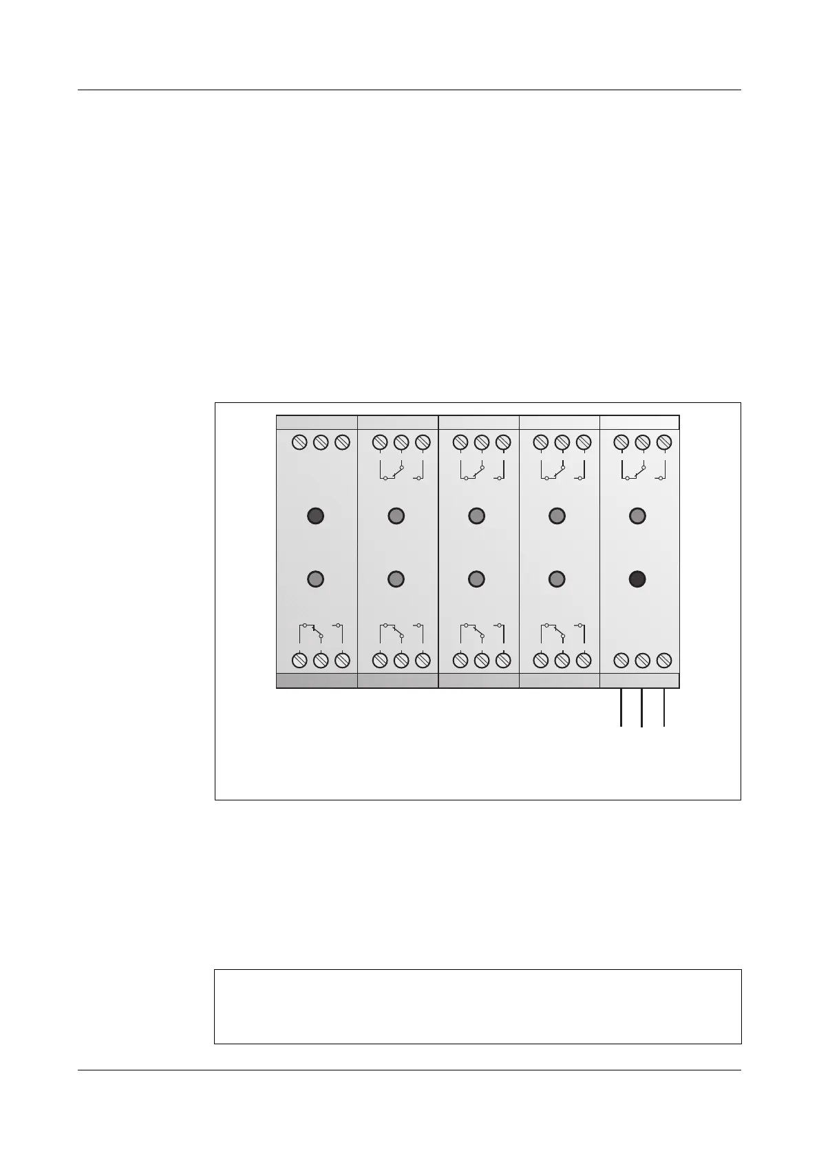
Connection The electrical connection is carried out like the connection to an RS485 inter-
face (the figure below shows ER8; see also
Operating Manual ER8/EL8,
B703564
).
Configuring
the module
h Activate the relay module via the setup program
Edit r Settings only via setup r Expanded configuration
This activates the menu Edit r External relay module.
h Configure the module
The functions are related to the relay module, but they also apply to the
logic module (Off = 0 V; On = 12 V).
If the module ER8/EL8 is connected to the interface, then no further
communication is possible via the interface.
Error
Power
(L+) (L-)
L1PE N
97
TxD
RxD RxD
TxD GND
98 99
K5 K6 K7 K8
4
4
1
4
4
2
4
4
3
2
4
1
2
4
2
2
4
3
1
4
1
1
4
2
1
4
3
K1 K2 K3 K4
3
4
1
3
4
2
3
4
3
3
1
3
2
3
3
8
4
1
8
4
2
8
4
3
7
4
1
7
4
2
7
4
3
6
4
1
6
4
2
6
4
3
5
4
1
5
4
2
5
4
3
Type 703580: Terminal strip 2, terminal 3 4 5
Type 703585: Terminal strip 2, terminal 3 4 5
If the setup plug is connected to the profile controller, the module will
not be operated and the outputs are in idle position (logic outputs:
0V).

 Loading...