43
9 Parameter level
General Two parameter sets can be stored.
Access level
by ...
h pressing
P 4 times in basic status or the manual operating mode.
Access code The level is protected by a code.
factory-set code: 0001
Selecting the
parameter set
Select the parameter set with
P.
PARAMETR ➔ PARASET1
Parameter Display Value range factory-
set
Meaning
Controller
structure
STR 1 P, I, PD, PI, PID PID Structure 2
1
refers to the second output in
the case of a double-setpoint controller.
With modulating controllers, only PI and
PID are possible.
STR 2 P, I , P D , P I , P I D P I D
Proportional
band
XP1 0—9999 digit 0 digit Size of the proportional band
If Xp1,2 =0 the controller structure is not
effective! (limit comparator action)
For proportional controllers, Xp1,2 must be
>0
XP2 0—9999 digit 0 digit
Derivative time TV1 0 — 9999 sec 80 sec Influences the differential component of
the controller output signal
TV2 0—9999 sec 80 sec
Reset time TN1 0 — 9999 sec 350 sec Influences the integral component of the
controller output signal
TN2 0—9999 sec 350 sec
Switching cycle
time
CY1 0—9999 sec 20 sec For a switching output, the cycle time
should be selected so that the switched
energy supply does not lead to impermissi-
ble measurement fluctuations, while, at the
same time, not overloading the switching
devices
CY2 0—9999 sec 20 sec
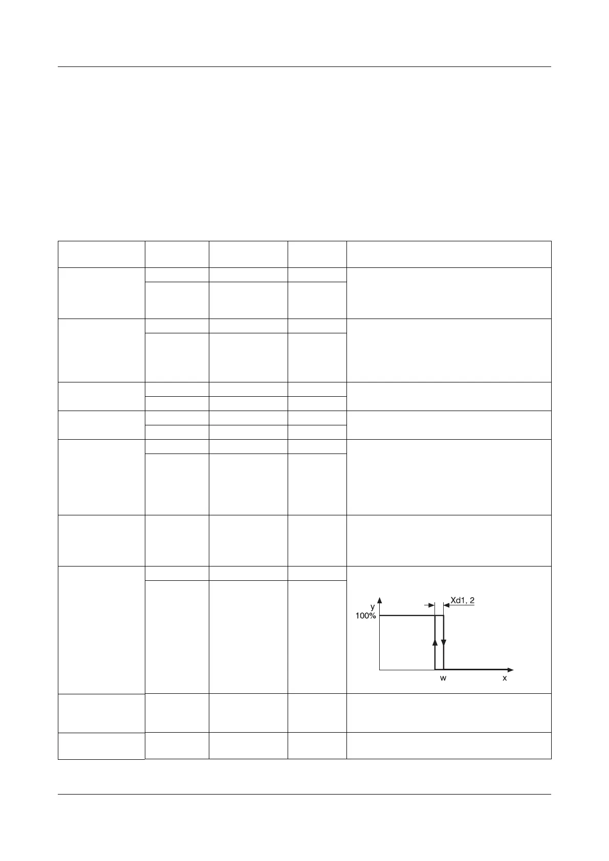
Contact spacing XSH 0 — 999 digit 0 digit Spacing between the two control contacts
for double-setpoint controllers, modulat-
ing controllers and proportional controllers
with integral actuator driver
Switching
differential
XD1 0—999 digit 1 digit Differential for switching controllers
for Xp = 0..
XD2 0—999 digit 1 digit
Stroke time TT 5—3000 sec 60 sec Utilised stroke time of the control valve on
modulating controllers and proportional
controllers with integral actuator driver
Working point Y0 -100 to +100% 0% Output for P and PD controllers
(y = Y0 at x = w).
1. Similarly, Xp2, Tv2, Tn2; Cy2; Xd2


 To Next Page