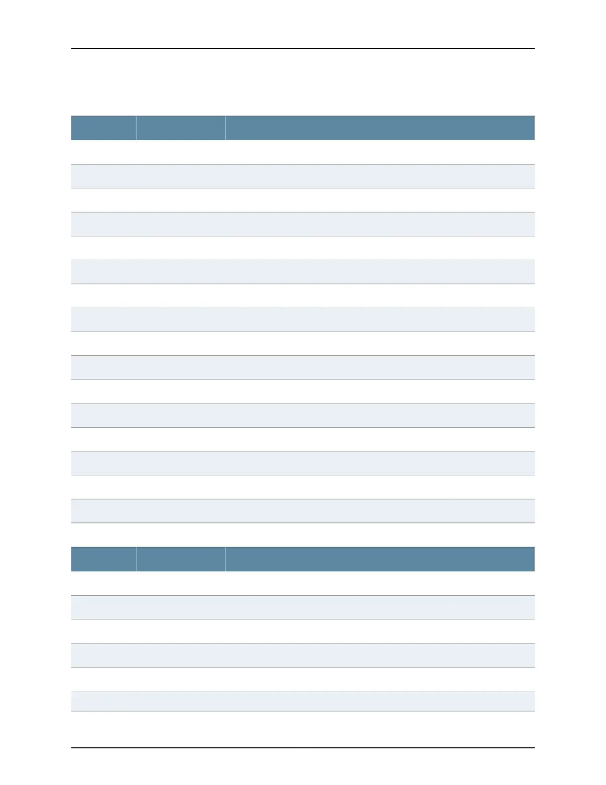
Table 46: SFP Network Port Connector Pinout Information (continued)
DescriptionSignalPin
2-wire serial interface clockSCL-5
Module absentMOD_ABS6
Rate selectRS7
Receiver loss of signal indicationRX_LOS8
Module receiver groundVeeR9
Module receiver groundVeeR10
Module receiver groundVeeR11
Receiver inverted data outputRD-12
Receiver noninverted data outputRD+13
Module receiver groundVeeR14
Module receiver 3.3 V supplyVccR15
Module transmitter 3.3 V supplyVccT16
Module transmitter groundVeeT17
Transmitter noninverted data inputTD+18
Transmitter inverted data inputTD-19
Module transmitter groundVeeT20
Table 47: SFP+ Network Port Connector Pinout Information
DescriptionSignalPin
Module transmitter groundVeeT1
Module transmitter faultTX_Fault2
Transmitter disabledTX_Disable3
2-wire serial interface data lineSDA4
2-wire serial interface clockSCL-5
Module absentMOD_ABS6
95Copyright © 2017, Juniper Networks, Inc.
Chapter 9: Pinout Specifications