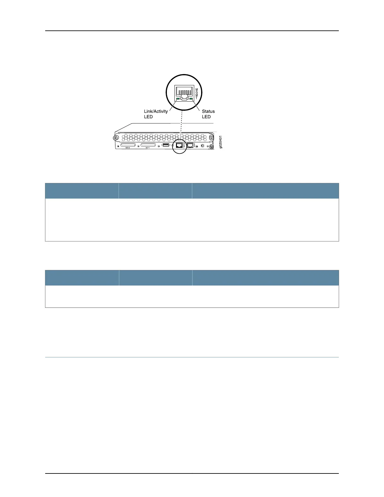
Figure 10: LEDs on the Management Port on an EX4200 Switch
Table 8 on page 24 describes the Link/Activity LED.
Table 8: Link/Activity LED on the Management Port on EX4200 Switches
State and DescriptionColorLED
•
Blinking—The port and the link are active, and there is link
activity.
•
On steadily—The port and the link are active, but there is no
link activity.
•
Off—The port is not active.
GreenLink/Activity
Table 9 on page 24 describes the Status LED (administrative status).
Table 9: Status LED on the Management Port on EX4200 Switches
State and DescriptionColorLED
•
On steadily—Administrative status is enabled.
•
Off—Administrative status is disabled.
GreenStatus
Related
Documentation
See Rear Panel of an EX4200 Switch on page 12 for port location.•
• Connecting a Device to a Network for Out-of-Band Management on page 157
Network Port LEDs in EX4200 Switches
Each network port on the switch has two LEDs. The four figures in this topic show the
location of those LEDs:
•
Figure 11 on page 25 shows the location of the LEDs on the network ports on the front
panel.
•
Figure 12 on page 25 shows the location of the LEDs on the uplink module ports on the
SFP uplink module.
Copyright © 2017, Juniper Networks, Inc.24
EX4200 Switch Hardware Guide