supply extend out of the chassis by 2.25 in. Power cord retainer clips extend out of the
power supply by 3 in.
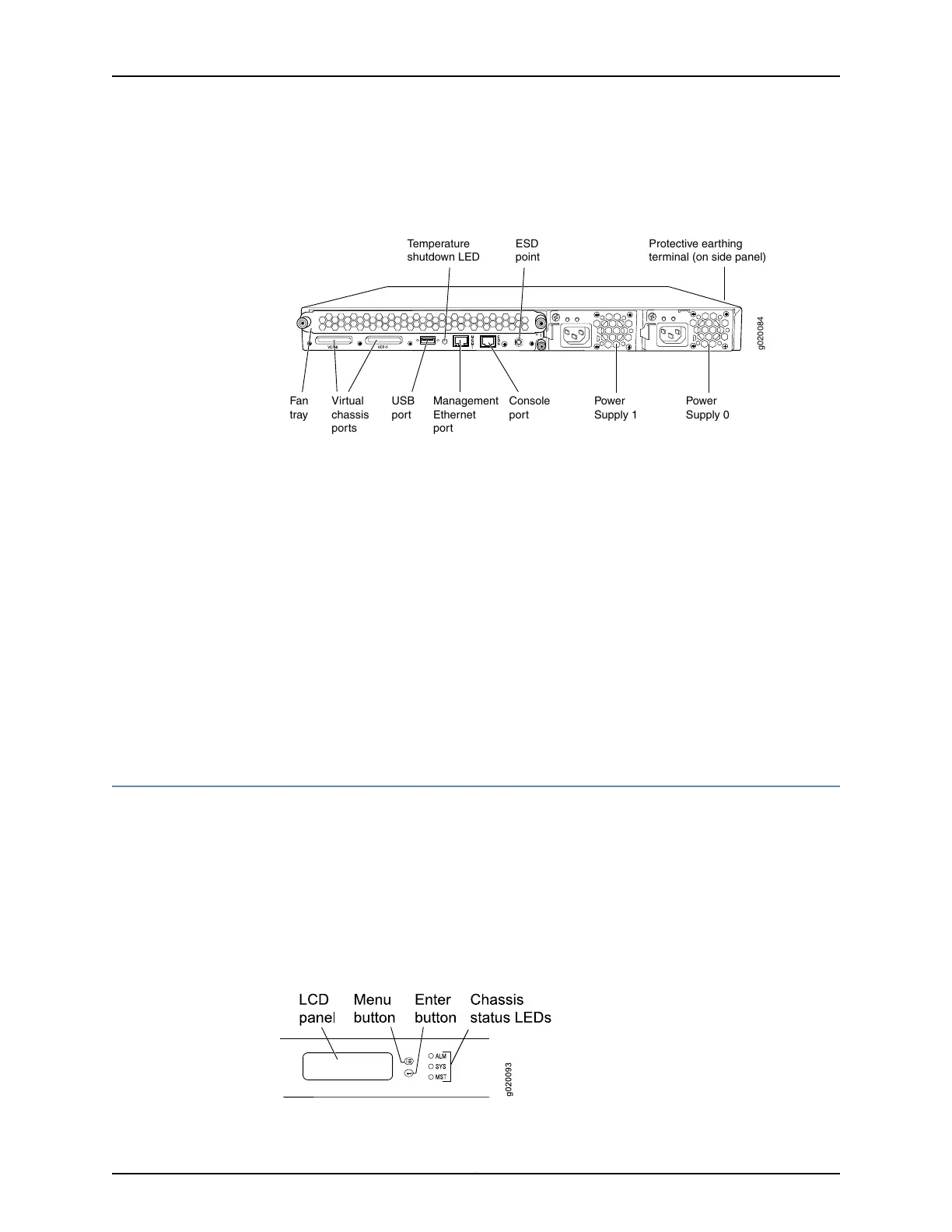
Figure 4: EX4200 Switch Rear Panel
g020084
Virtual
chassis
ports
USB
port
Management
Ethernet
port
Fan
tray
Console
port
Power
Supply 1
Power
Supply 0
Protective earthing
terminal (on side panel)
ESD
point
Temperature
shutdown LED
Related
Documentation
Field-Replaceable Units in EX4200 Switches on page 10•
• Front Panel of an EX4200 Switch on page 11
• USB Port Specifications for an EX Series Switch on page 92
• Cooling System and Airflow in an EX4200 Switch on page 31
• Power Supply in EX4200 Switches on page 33
• Prevention of Electrostatic Discharge Damage on page 273
• Connecting Earth Ground to an EX Series Switch on page 143
• Installing and Removing EX4200 Switch Hardware Components on page 140
• Understanding EX4200,EX4500, and EX4550 Virtual Chassis Hardware Configurations
on page 111
LCD Panel in EX4200 Switches
The LCD panel on the front panel of the switch shows two lines of text, each of which
can contain a maximum of 16 characters. The LCD panel displays a variety of information
about the switch and also provides a menu to perform basic operations such as initial
setup and reboot.
There are two navigation buttons—Menu and Enter—to the right of the LCD panel.
See Figure 5 on page 13.
Figure 5: LCD Panel
13Copyright © 2017, Juniper Networks, Inc.
Chapter 2: Chassis Components and Descriptions