NOTE: The interfaces for the two dedicated VCPs are operational by default.
However, if you are using the uplink module portsasVCPs, you must explicitly
set the uplink module ports to function as VCPs.
The following illustrations describe various Virtual Chassis cabling configuration examples.
NOTE: For increased availability and redundancy, we recommend that you
always configure your Virtual Chassis in a ring topology.
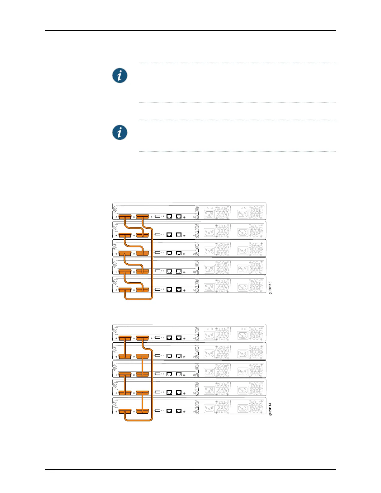
Figure 24 on page 117 and Figure 25 on page 117 show five EX4200 switches stacked
vertically in a rack and interconnected in a ring topology using four short Virtual Chassis
cables and one long Virtual Chassis cable.
Figure 24: EX4200 Switches Mounted on a Single Rack and Connected
in a Ring Topology Using Short and Long Cables: Option 1
Figure 25: EX4200 Switches Mounted on a Single Rack and Connected
in a Ring Topology Using Short and Long Cables: Option 2
117Copyright © 2017, Juniper Networks, Inc.
Chapter 10: Planning the Virtual Chassis