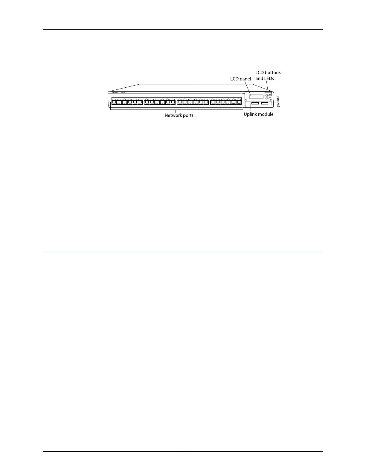
Figure 3: EX4200-24F Switch with 24 SFP Ports
Related
Documentation
Chassis Status LEDs in EX4200 Switches on page 21•
• Rear Panel of an EX4200 Switch on page 12
• Network Port LEDs in EX4200 Switches on page 24
• RJ-45 Port, QSFP+ Port, SFP+ Port, and SFP Port Connector Pinout Information on
page 94
• LCD Panel in EX4200 Switches on page 13
• Pluggable Transceivers Supported on EX4200 Switches on page 79
• Installing and Removing EX4200 Switch Hardware Components on page 140
• Installing an Uplink Module in an EX4200 Switch on page 187
• Removing an Uplink Module from an EX4200 Switch on page 189
Rear Panel of an EX4200 Switch
The rear panel of the EX4200 switch accomdates the following components:
•
Fan tray
•
Virtual Chassis ports (VCPs)
•
USB port
•
Temperature shutdown LED
•
Management Ethernet port
•
Console port
•
ESD point
•
Power supply or power supplies
Figure 4 on page 13 shows the rear panel of an EX4200 switch with power supplies and
fan tray installed. The rear panel of all the EX4200 switches except EX4200-24F-S and
EX4200-48T-S switches are similar. All EX4200 switches except the EX4200-24F-S
and EX4200-48T-S switches are shipped with the power supplies and fan tray
pre-installed in the rear panel of the switch. The power supplies and the fan tray for the
EX4200-24F-S and EX4200-48T-S models are not shipped by default; you must order
them separately and install them in the rear panel. The 320 W AC power supply and the
190 W DC are flush with the chassis. The 600 W AC power supply and 930 W AC power
Copyright © 2017, Juniper Networks, Inc.12
EX4200 Switch Hardware Guide