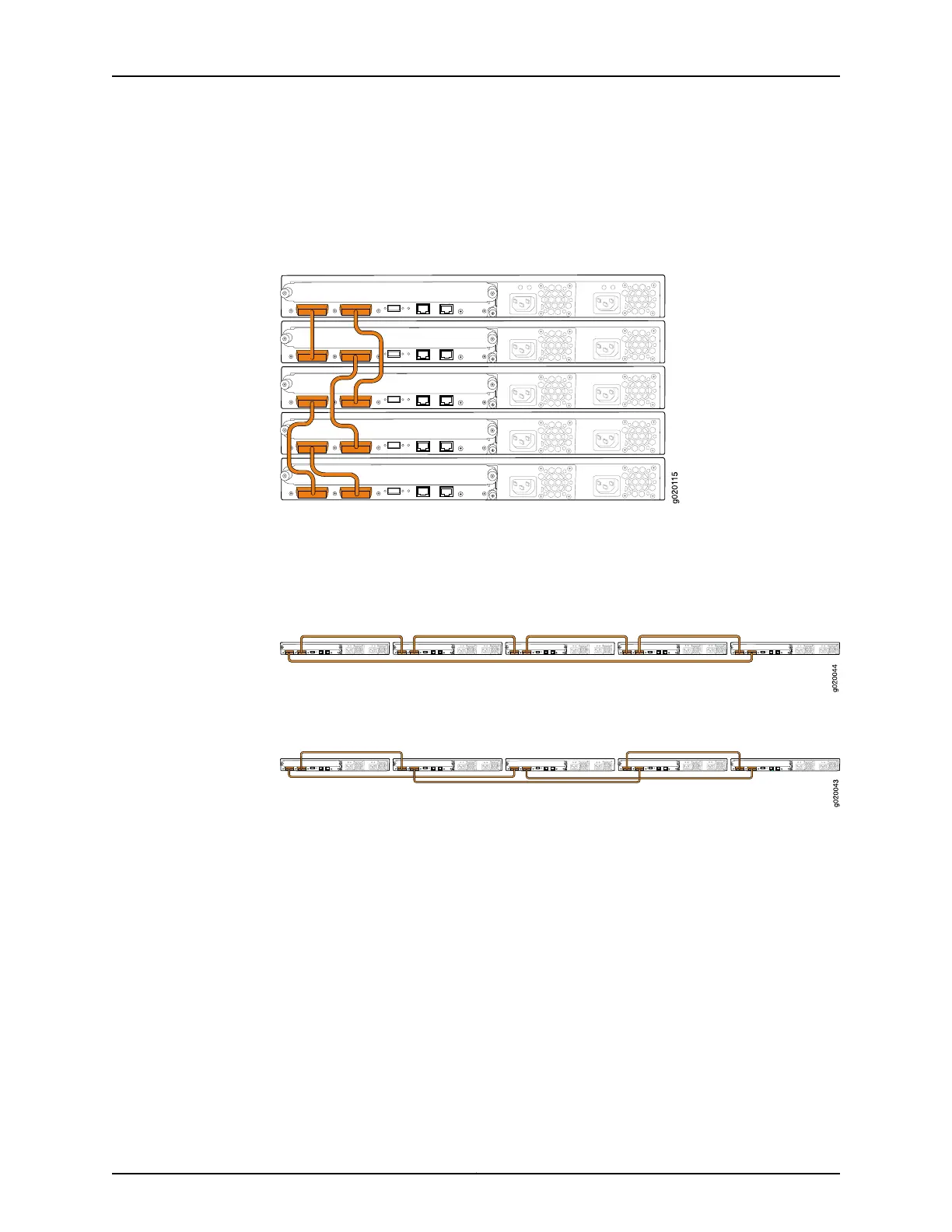
Figure 26 on page 118 shows five EX4200 switches stacked vertically in a rack and
interconnected in a ring topology using short-length and medium-length Virtual Chassis
cables.
Figure 26: EX4200 Switches Mounted on a Single Rack and Connected
in a Ring Topology Using Short and Medium Cables
Figure 27 on page 118 and Figure 28 on page 118 show five EX4200 switches mounted on
the top rows of adjacent racks and interconnected in a ring topology using medium-length
and long-length Virtual Chassis cables.
Figure 27: EX4200 Switches Mounted on Adjacent Racks and Connected
in a Ring Topology Using Medium and Long Cables: Option 1
Figure 28: EX4200 Switches Mounted on Adjacent Racks and Connected
in a Ring Topology Using Medium and Long Cables: Option 2
Related
Documentation
• Understanding EX4200,EX4500, and EX4550 Virtual Chassis Hardware Configurations
on page 111
• Understanding EX Series Virtual Chassis Components
• Planning EX4200, EX4500, and EX4550 Virtual Chassis on page 114
• Virtual Chassis Ports Connector Pinout Information for EX4200 Switches on page 107
• Example: Configuring an EX4200 Virtual Chassis Interconnected Across Multiple Wiring
Closets
Copyright © 2017, Juniper Networks, Inc.118
EX4200 Switch Hardware Guide