7
ANTRIEBSTECHNIK
11
17
11
LWL - BUS
Name: Option
05.01.99
Chapter Section PageDate
© KEB Antriebstechnik, 1998
All Rights reserved
Networks
Network Hardware
START
STOP
FUNC.
SPEED
ENTER
F/R
START
STOP
FUNC.
SPEED
ENTER
F/R
START
STOP
FUNC.
SPEED
ENTER
F/R
START
STOP
FUNC.
SPEED
ENTER
F/R
2
3
5
2
3
7
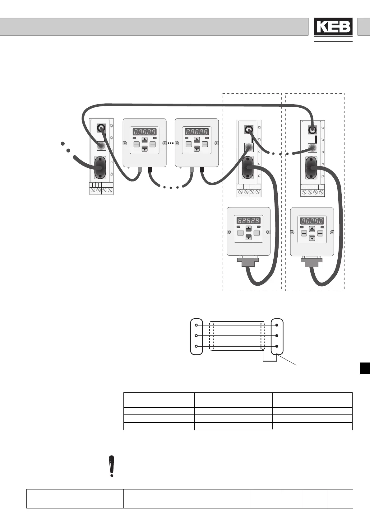
00.F4.028-1009 00.F4.010-A009 00.F4.010-A009 00.F4.028-1008
00.F4.028-1008
00.F4.010-1009 00.F4.010-1009
Master Slave Slave
Slave Slave
Number of users = 1 ... 239
Connection
Optical Fibre BUS
Permissible Line Length
between the Users
Cable damping Switch position A Switch position B
0,3 dB 0 ... 42 m 3 ... 55 m
0,2 dB 0 ... 63 m 3 ... 83 m
0,1 dB 0 ... 127 m 6 ... 167 m
Tested transfer rate ➯ 115 kBaud
PC or SPS
9-pole Sub-D Socket 9-pole Sub-D Connector
Housing (PE)
Switch position A must be used for an ambient temperature > 35 °C.
Connection of Optical
Fibre Interface to PC
(or Master)
Optical Fibre
Interface Master
(Operator)
PC
(Optical Fibre
Interface Slave)
The installation is possible with optical fibre
operators and/or units with optical fibre interface
and interface operator.

 Loading...
