GB - 74
Installation
6. Installation
6.1 EMC-compatible control cabinet installation
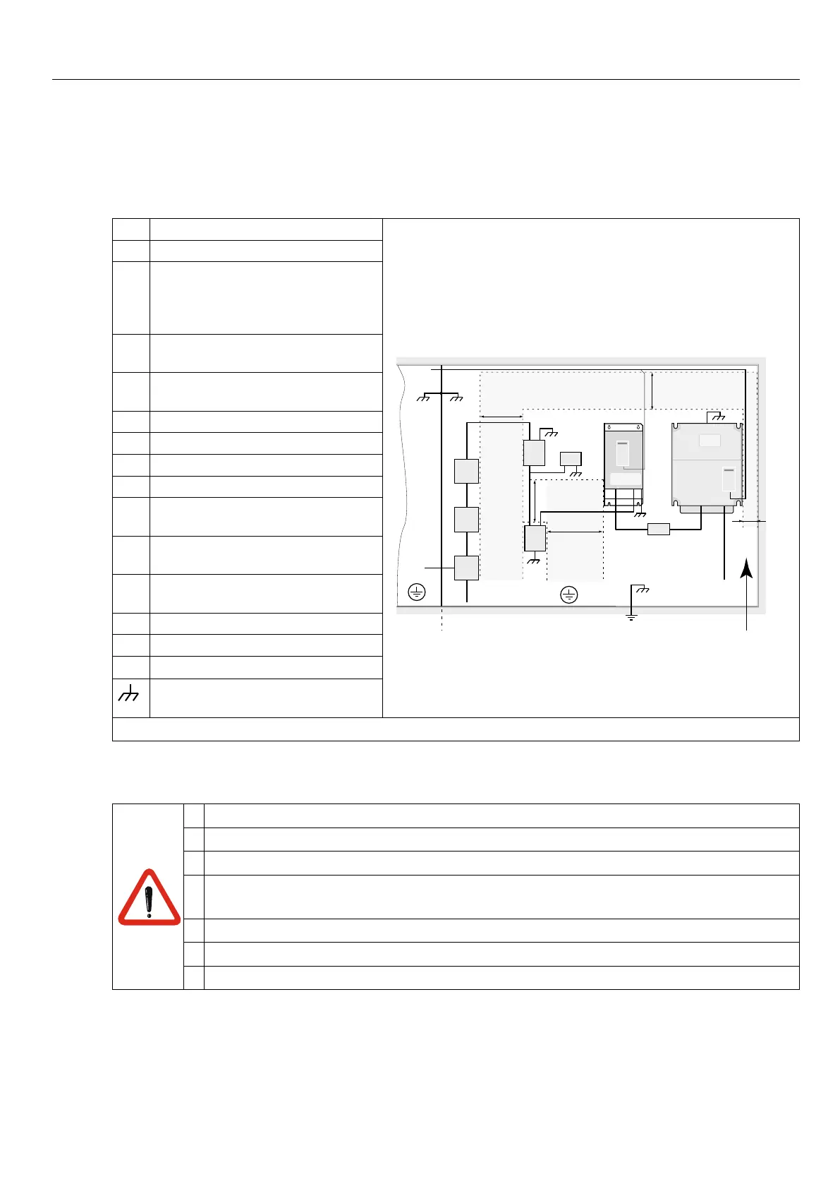
1 Mains fuse
150 mm
30 mm
150 mm
1
2
8
10b
9b
10a
10c
11
11a
12
4
3
5
150 mm
150 mm
6
7
9a
Control circuit Power circuit
Direction of the
coolingns
2 Main contactor
3 HF-side-mountedlter(≥size25
R-SorR6-N)
HF-sub-mountedlter(≤size19
R6-S)
4 if necessary external synchroniza-
tion
5 Commutation reactor / harmonic
lter
6 COMBIVERT R6
7 if necessary external DC fuses
8 Frequency inverter
9 Motor lines
10
A
ProtectiveEarth(PE)onthe
mounting plate power circuit
10b ProtectiveEarth(PE)onthe
mounting plate control circuit
10c Equipotential bonding with the
housing earth
11 Mains connection power circuit
11 A Mains connection control circuit
12 Control lines
Large area contact at the mounting
plate
Figure 26: EMC-compatible control cabinet installation
6.2 Installation instructions
• Stationarily install and earth COMBIVERT.
• The device must not be permeated by mist or water.
• Allowforsufcientheatdissipationifinstalledinadust-proofhousing.
• Install the COMBIVERT in an appropriate housing in accordance with the local
regulations when operating it in explosion-endangered spaces.
• Protect COMBIVERT against conductive and aggressive gases and liquids.
• The lines of the R6-S commutation reactor must be limiting to 50 cm.
• The frequency inverters must be placed in the immediate vicinity of the R6-S.

 Loading...
