GB - 89
Connection of the control board version S
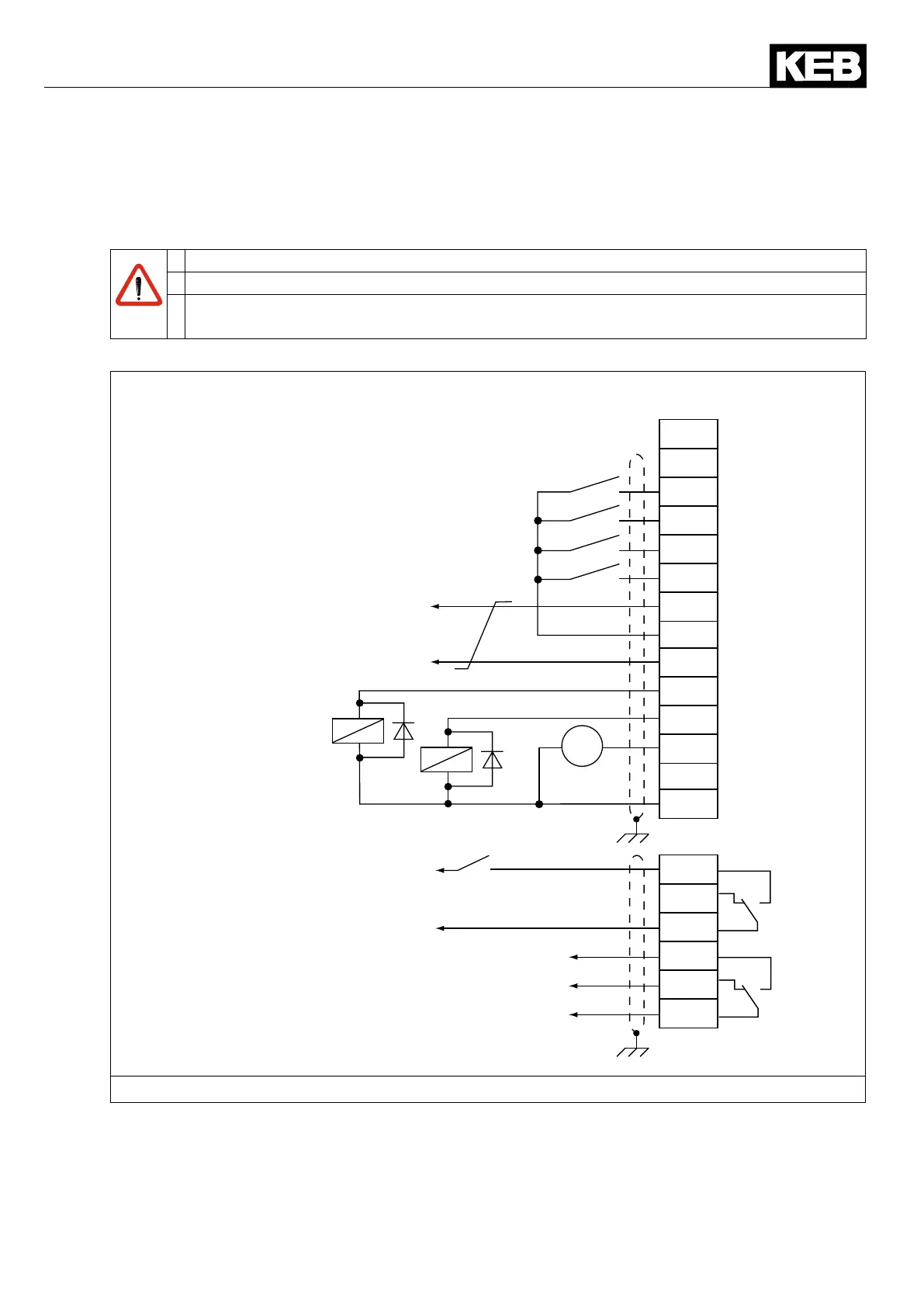
6.5.4 Wiring example
In order to prevent a malfunction caused by interference voltage supply on the control inputs,
thefollowingdirectionsshouldbeobserved:
EMC
• Use shielded/drilled cables
• Lay shield on one side of the inverter onto earth potential
• Laycontrolandpowercableseparately(about10...20cmapart);laycrossingsin
a right angle
U
X2A
10
11
12
13
14
15
16
17
18
16
18
19
20
21
22
23
24
25
26
27
28
29
max. 25 mA DC
per digital output
Analog output
0…±10 V DC / 5 mA
max. 30 V DC
0.01…2 A
max. 30 V DC
0.01…2 A
Active signal for further R6-S
units at parallel operation
Supply voltage of the inverter
inputs
Control release inverter
Figure 38: Wiring example R6-S
 Loading...

