GB - 100
Appendix A
A. Appendix A
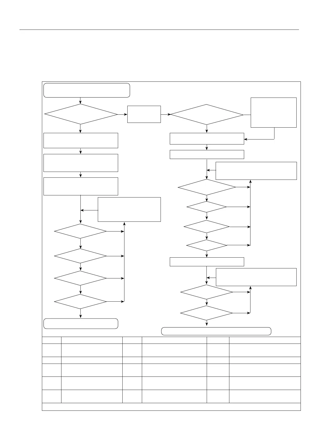
A.1 Dimensioning power supply and regenerative units
Dimensioning of the power supply
and regenerative unit
Only
regeneration ?
DecouplingR6-S(see4.4.3to
4.4.5)
Acquire:
PM,PMmax,t1,T,ηM,ηG,ηFI
Calculate:
ILG, ILGmax
IDCmax > ILGmax
select higher unit or paral-
lel connection of R6-S
(n•IDC,n•IDCmax)
t1 > 60 s
Regenerative unit capable
T<300s
IDC > ILG
yes
yes
no
yes
no
yes
no
yes
no
Acquire:
CZK_all
CZK_all>CZK_max
Acquire:
PM, PMmax,t1,T,ηM, ηG, ηFI
Calculate:ILM,ILMmax
IDCmax > ILMmax
select higher unit or parallel con-
nection of R6-S
(n•IDC,n•IDCmax)
t1 > 60 s
T<300s
IDC > ILM
yes
no
yes
no
yes
no
yes
no
Calculate:ILG,ILGmax
IDCmax > ILGmax
IDC > ILG
yes
no
yes
no
select higher unit or parallel con-
nection of R6-S
(n•IDC,n•IDCmax)
Power supply and regenerative unit capable
bridgeover ext.
load-shunt with
contactor(special
unit)
no yes
no
PM Mechanical power η
M Motorefciency IDC DC output current R6-S
PM-
max
Max. mechanical power ηG Gearboxefciency IDCmax max. DC output current
R6-S
t1 Overload time ηFU Inverterefciency ILG DC load regenerative current
t Last cycle ILM DC load motoric current ILGmax Max. DC load regenerative
current
n Number R6-S ILM-
max
Max. DC load motoric
current
CZK_all DC link capacity of all fre-
quency inverters
CZK_
max
max. connecting capacity
R6-S
Figure 39: Dimensioning power supply and regenerative units

 Loading...
