GB - 81
Connection Power Unit R6-S
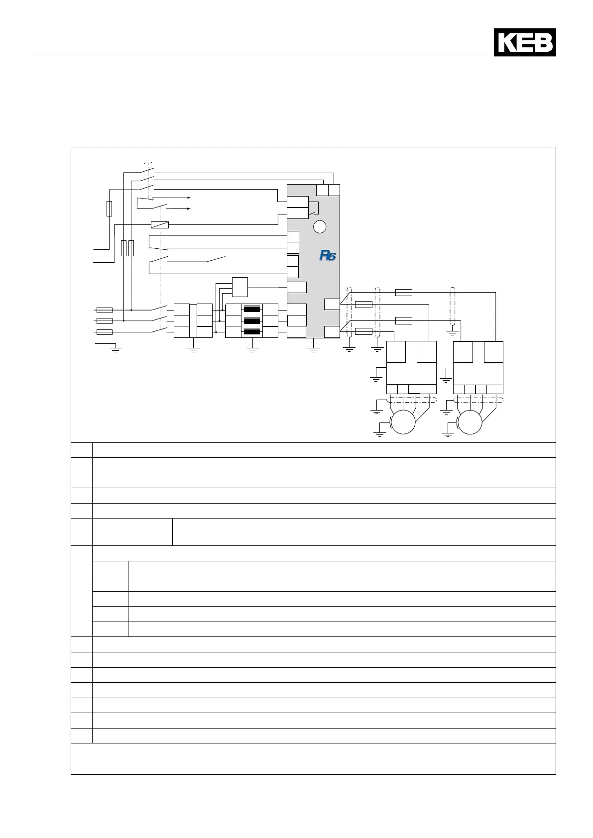
6.4.2 Powersupplyandregenerativeoperationatinvertercurrents≤currentofoneCOM-
BIVERT R6-S
N
L
L2.1
L1.1
L3.1
++
- -
L3.2
L2.2
L1.2
L3.2
L2.2
L1.2
24
25
21
22
12
17
43
44
13
14
L1
L2
L3
L1
L2
L3
L1’
L2’
L3’
PE
L2 L1
13/K2
14/K2
A2
A1
X1A
X2C
X1B
X1B
S1
F1
F2
K1
HF
A1
DR
H1
S2
H1
G1
X2B
L3
X2B
L2
L1
X2A
xx
xx
xx
xx
PE
U
V
W
PE
U
V
W
F4 F4
G2 G2
M M
F3
A1 Synchronizationunit(max.lengthofthephaselines1m)
DR Commutationreactor/harmoniclter
F1 Mains fuses type gR
F2 10 A fuse gG/gL or automat characteristic K
F3 10 A fuse gG/gL
F4 DC fuses type
aR/gR
ThecablecrosssectionaswellastheDCfuses(seechapter2.1)mustbedimen-
sionedtotheDCratedcurrentoftheload(seetechnicaldataoftheinverter).
G1 Regenerative unit COMBIVERT R6-S
X1A Power circuit terminals
X1B Connection for precharging and switching-on of line contactor K1
X2A Controlterminalstrip(X2A.12:controlrelease;X2A.17:voltageoutput)
X2B Connection for synchronization line
X2C Activationoftheself-holdingoftheloadshuntrelay(K2internal)
G2 Frequencyinverteralltypes(see4.3.1)
H1 Error message contactor K1 not dropped
HF Radiointerferencelter
K1 Line contactor with auxiliary contacts
M Motor
S1 Onswitch/contactor(400V/16AAC3)
S2 Realize control release with PLC or pre-charging contactor / -switch
Figure 34: Power supply and regenerative operation at inverter currents ≤ current of one
COMBIVERT R6-S
 Loading...

