GB - 79
Connection of the COMBIVERT R6
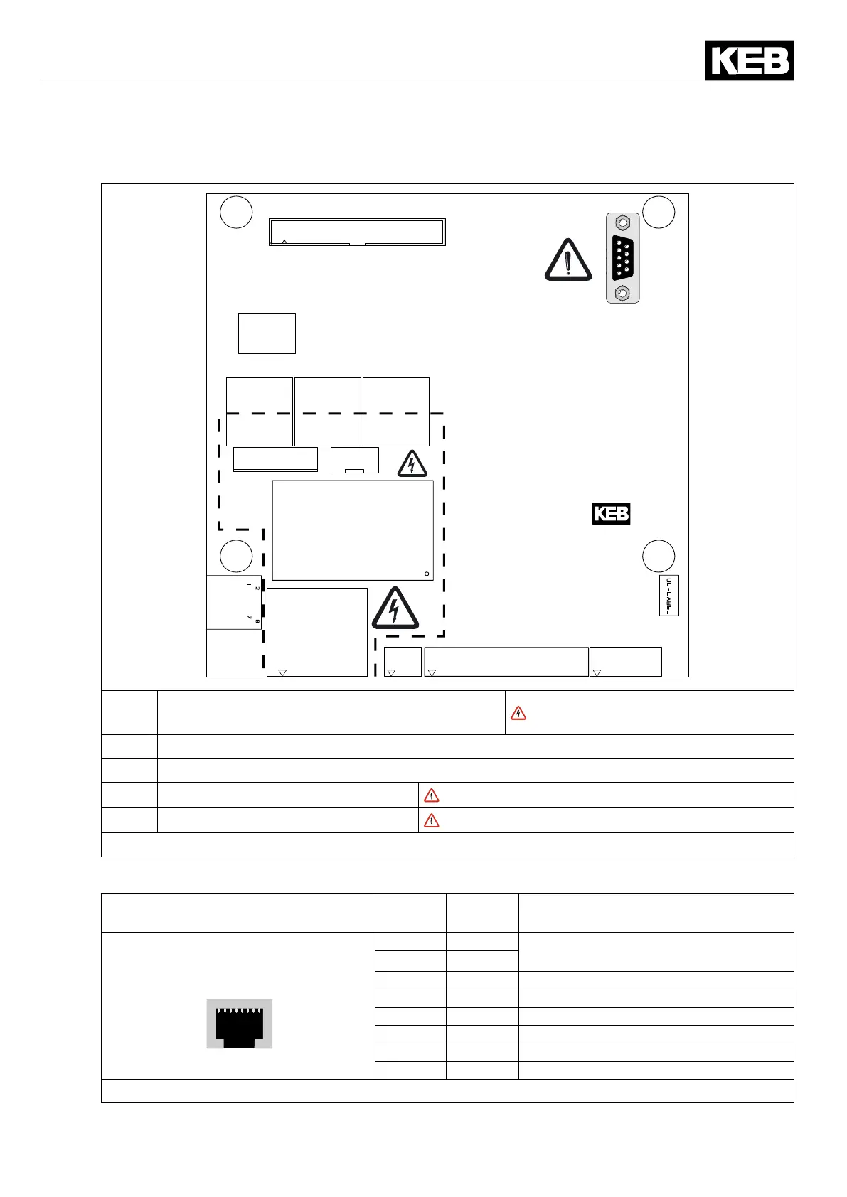
6.3.4 Connections of the control board
X2A.10...23
X2A.24...29
X1B
X2C
X2B
X4B
X1B
Mainscontactor(AC15:6A230VAC/DC13:
6A24VDC)andconnectionprecharging
Supplyvoltagepotential!
X2B Connection for synchronization line
X2C Activation of the line contactor self-holding
X4B HSP5 operator interface
No direct PC connection
X2A Control terminal strip
Installcontrolandmainscableseparately!
Figure 31: Connection terminals of the control board
6.3.5 Connection of the synchronization unit
RJ45 socket for phase synchroni-
zation and temperature sensor
No. Name Function
1 8
X2B
X2B.1 t1 Connection for temperature sensor
(option)
X2B.2 t2
X2B.3 U13_syn Synchronization phase 1 / 3
X2B.4 – reserved
X2B.5 U21_syn Synchronization phase 2 / 1
X2B.6 – reserved
X2B.7 U32_syn Synchronization phase 3 / 2
X2B.8 – reserved
Figure 32: RJ45 socket for phase synchronization and temperature sensor
 Loading...

