GB - 77
Connection of the COMBIVERT R6
6.3.2 Connection terminals of the power circuit
AllterminalstripsmeettherequirementsonEN60947-7-1(IEC60947-7-1)
View of power supply and regenerative units
The terminals of a power supply and regenerative unit can be input or output
dependentontheactualoperatingstatus(powersupplyorregeneration).Forthe
standardization of the view the line side is always regarded as input and the DC
voltage side is always regarded as output.
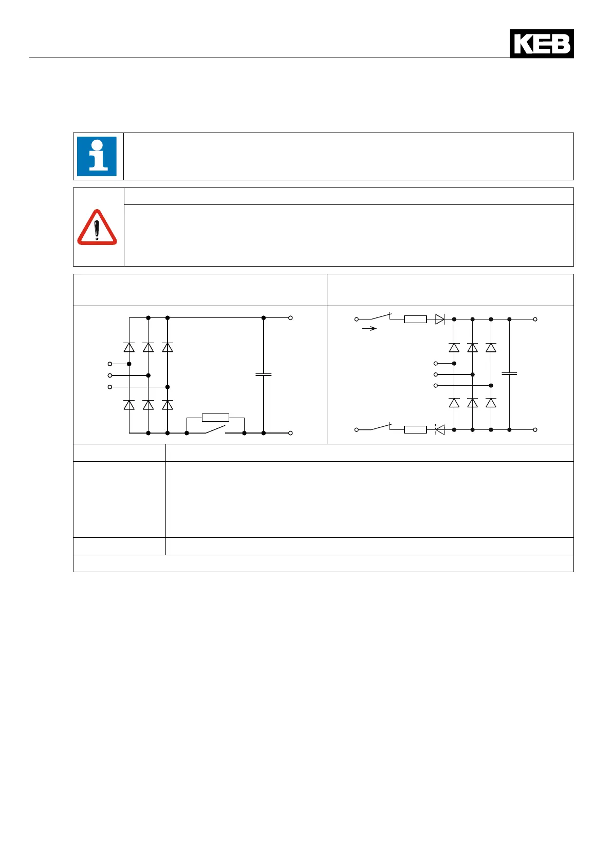
R6-S in E housing R6-S in R and P housing without internal
DC fuses
+
++
--
L1.2
L2.2
L3.2
+
++
--
L1
L2
L1.2
L2.2
L3.2
I_LSF
Terminals Description of terminals at KEB inverters
++, – – DC voltage output with starting current limiting for loading the connected
inverter; usable as input for regenerative operation. If inverters with mains
supplyoftypeA1orA2(see4.3.1)areavailableintheDCbus,thesemay
be switched to mains only after loading the DC bus. Note the maximum
DClinkcapacityordecouplingdiodes!
L1.2, L2.2, L3.2 Mains input 3-phase coming from the commutation reactor
Figure 28: Description of the input terminals of the COMBIVERT R6

 Loading...
