E 36
8. Parameter Description
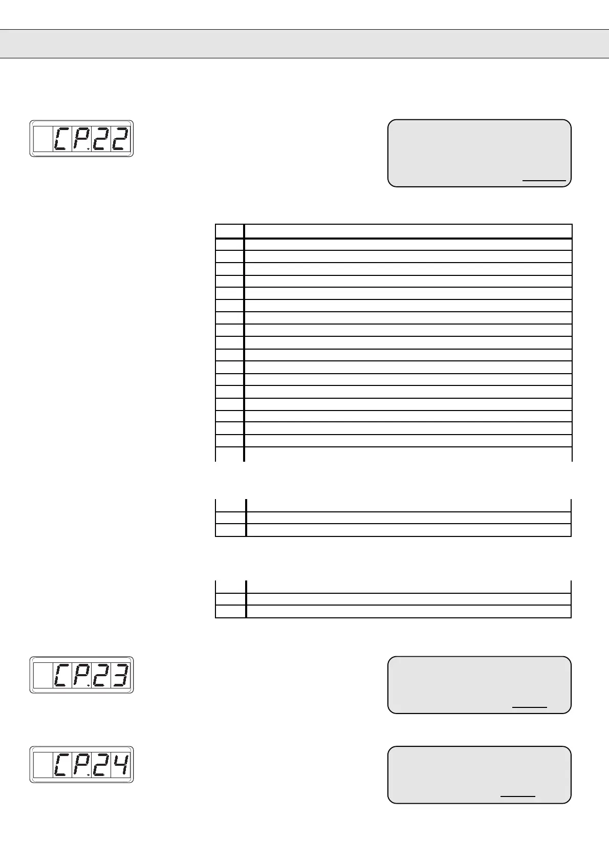
Switching Condition
Output D2
Defines the switching condition of
digital output D2.
Setting range: 0…20
Resolution: 1
Factory setting: 18
Remarks: ENTER–Parameter
Customer setting:
! Refer to table below !
Switching Conditions
Digital output D1 and D2
Value Switching condition
0 always active
1 always active
2 system switched on; no abnormal operating condition
3 ready for operation and modulation enabled
4 abnormal operating condition / Fault (CP.2 = A.xxx or E.xxx)
5 inverter blocking after fault (E.xxx)
6 prewarning level electr. protective motor relay (OH.2) exceeded
7 after triggering of motor PTC-contact
8 prewarning level OH.2 or dOH exceeded
9 current controller in limitation
10 speed controller in limitation
11 any controller in limitation
12 drive in acceleration phase
13 drive in deceleration phase
14 drive runs with constant speed
15 drive runs with constant speed except speed 0
16 clockwise rotation – not at noP, LS, abnormal stopping or fault
17 anti-clockwise rotation - not at noP, LS, abnormal stopping or fault
18 actual speed > 0,1 x rated speed
19 apparent current > rated current
20 torque > torque level CP.23
Only digital output D1
Only digital output D2
18 actual speed > speed level CP.24
19 apparent current > rated current
20 torque > rated torque
Torque Level Output D1
Defines the torque level of digital
output D1.
Setting range: 0…50 Nm
Resolution: 0,1 Nm
Factory setting: 0,5 x M
Rated
Customer setting: Nm
Speed Level Output D2
Defines the speed level of digital
output D2.
Setting range: 0…16000 U/min
Resolution: 0,5 U/min
Factory setting: 0,5 x n
Rated
Customer setting: U/min

 Loading...


