14 Getting Started Guide
Introduction
Overview
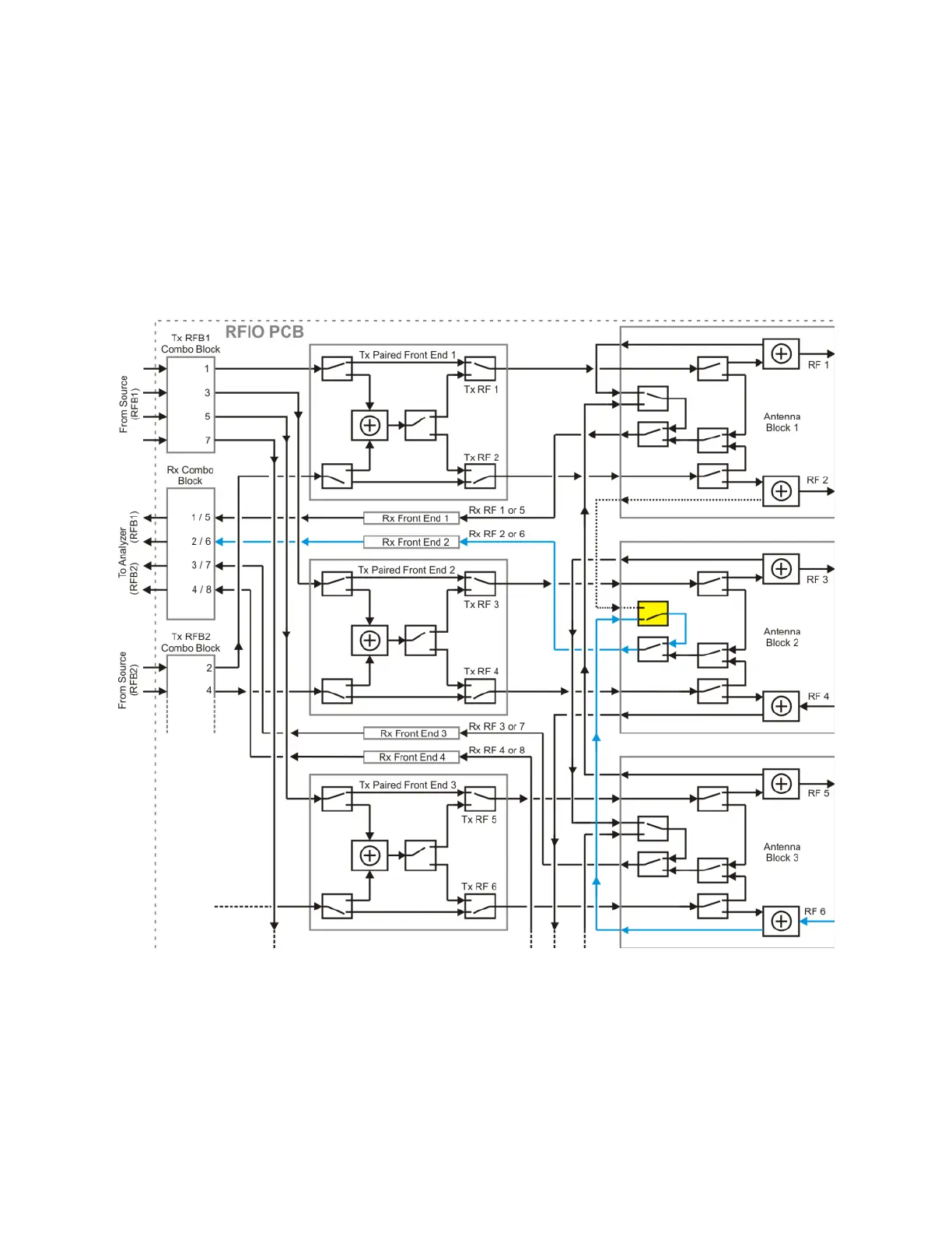
The diagram below shows how receive signals are routed from the front panel
RF ports. The signal routing is more complex than in the case of transmit
signals. The receive path from either of two RF ports (RF 2 or RF 6, in this
example) must go through the switch highlighted in yellow. The receive signal
furnished to the Rx combination block must come from port RF 2 or port RF 6,
but not both at once. That is why there cannot be more than four receive ports
used at once.
Figure 1-5 Rx path from the front panel RF ports
The remaining RF ports follow a similar pattern. The remaining receive paths to
the Rx combination block can come from RF 1 or 5 (not both), RF 3 or 7 (not
both), and RF4 or 8 (not both).

 Loading...