E8257D/67D, E8663D PSG Signal Generators Service Guide 411
Post–Repair Procedures
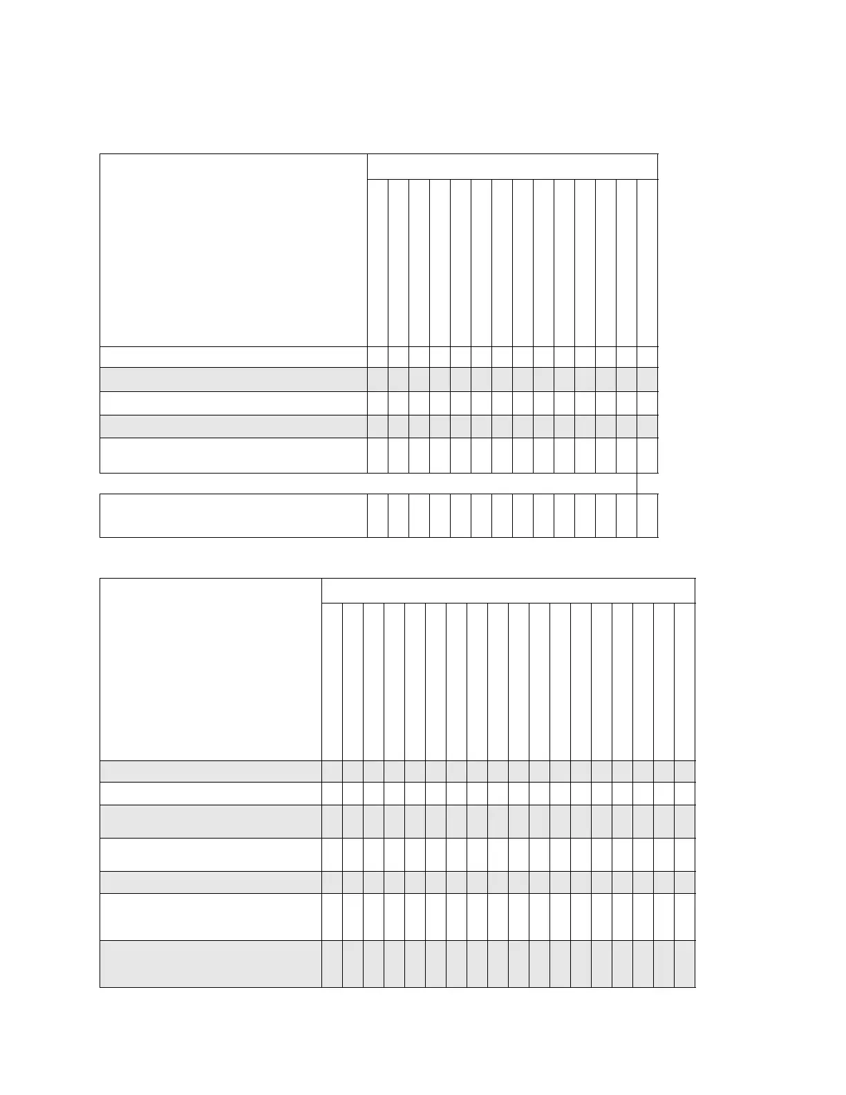
Post–Repair Procedures Matrix
Sub–Harmonic Spurious X X X
Non–Harmonic Spurious
X X
X X X
X
Single–Sideband Phase Noise
X
X X
EVM and IQ Offset
X
X
External Digital Modulation Level Accuracy
Relative to CW
X X
Optional Performance Test
Timebase Aging Rate
X
Table 4-10 Performance Tests: Assemblies A1—A17 (For prefixes >= xx4928)
Performance Tests
The
following performance tests are listed in the
order that they should be performed to minimize
changes in test equipment configurations.
Replaced Assembly
A1 Keyboard
A2 Display
A2DS1 Backlight
A3 Power Switch
A4 Inverter
A5 Sampler
A6 Frac–N
A7 Reference (Standard)
A7 Reference (Option UNR/UNX)
A8 Output (Analog)
A8 Output (Digital)
A9 YIG Driver
A10 ALC
A11 Pulse/Analog Mod Gen
A12 Lowband Fast Pulse
A13 IQ Multiplexer
A14 Baseband Generator
A17 Baseband Generator Interface
Self Check Test
X X X X X X X X X X X X X X
X X X
X
Maximum Leveled Output Power
X X X X
Maximum Leveled Output Power - Digital Mode
(E8267D Option HBL Only)
X
Maximum Leveled Output Power - Wide IQ/FM
Mode (E8267D Option H18 Only)
X
Power Level Accuracy
X X X
Internal Pulse Modulation Level Accuracy
(E8257D/E8267D Option UNU, UNW, UNS, or HNS,
and E8663D Only)
XX XX
Internal Pulse Modulation Rise/Fall Time
(E8257D/E8267D Option UNW, UNS, or HNS,
E8663D Option UNW)
X X X
Table 4-9 Performance Tests: Assemblies A30—A40, AT1, B1, and RF Output Connector
(For Prefixes < xx4928)
Performance Tests Replaced Assembly
The following performance tests are listed in the order that
they should be performed to minimize changes in test
equipment configurations.
A30 Mod Filter with High Power
A30 Mod Filter with Standard Power
A31 Motherboard
A32 10 MHz Crystal Oscillator
A34 Internal Hard Drive
A35 3 − 20 IQ Modulator
A36 Quadraplier
A37 Up Converter
A38 Lowband Switch Filter
A39 Directional Coupler
A40 Compact Flash Drive
AT1 115 dB Attenuator
B1 Fan
RF Output Connector