78 E8257D/67D, E8663D PSG Signal Generators Service Guide
Troubleshooting
Troubleshooting Assembly–Level Problems
1200 Power Supply
1. Press View Test Info and highlight Self Test 1200. Press View Details.
2. From the displayed self–test results, determine which supply or supplies
failed.
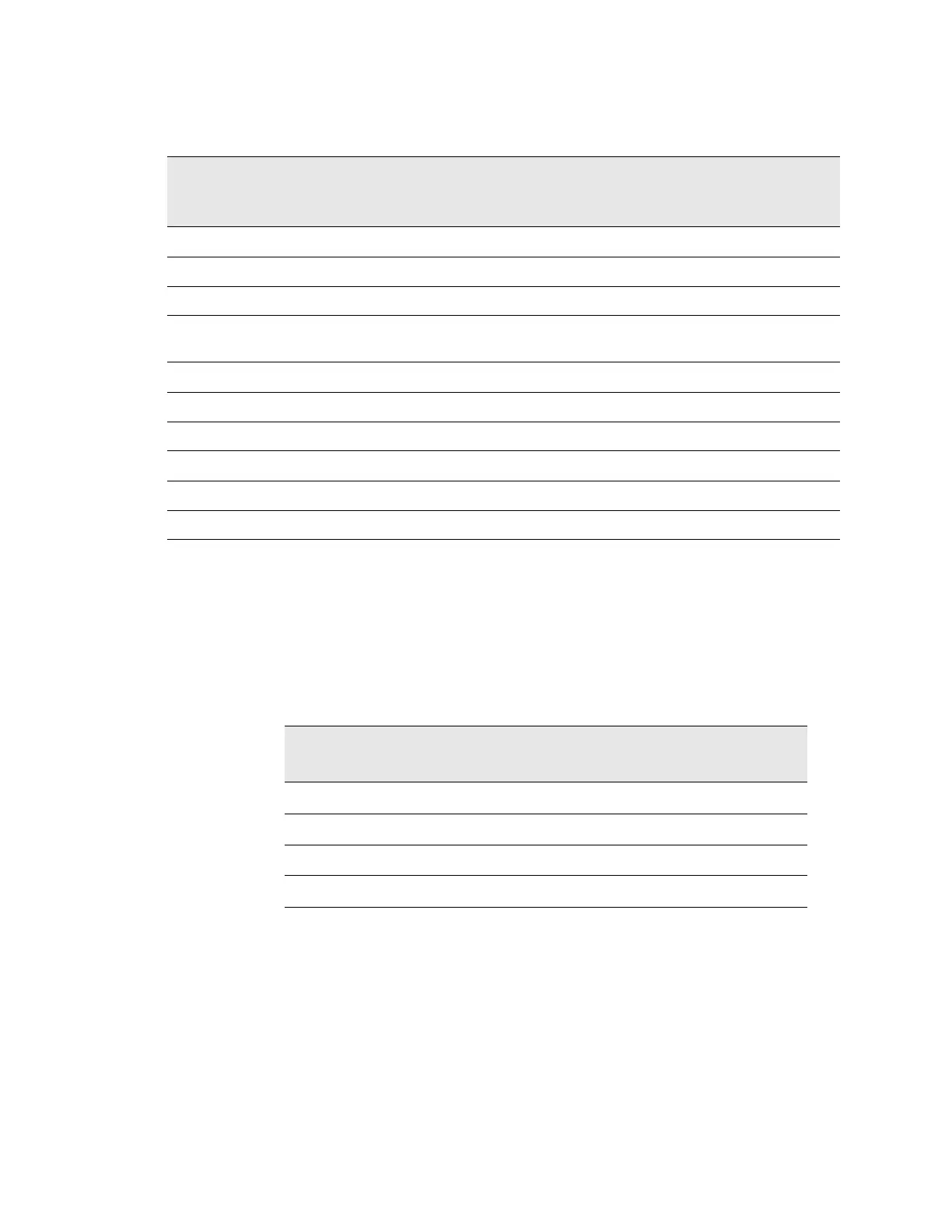
3. Refer to the following table; disconnect one microcircuit at a time and run
self–test 1200.
— If the test passes after disconnecting one or more microcircuits,
replace the microcircuit.
— If self–test still fails after disconnecting all the microcircuits,
replace the A26 MID.
1201 Mod Filter
1. Disconnect the cable between the A23 Lowband Coupler/Detector and the
A30 Modulation Filter, and connect a spectrum analyzer to the cable.
Supply
Voltage
(Vdc)
E8257D
Connector
Pins
All Other Models
Connector
Pins
Minimum
Value
(Vdc)
Maximum
Value
(Vdc)
Origin
+32 P201–11 P201–1 +31.04 +32.96 Main Supply
+15 P201–12, 13, 14 P201–2, 3, 4 +14.55 +15.45 Main Supply
–15 P201–21, 22 P201–11, 12 –15.45 –14.55 Main Supply
+5.2 P201–7, 8, 9, 10, 23, 24, 25,
26, 27, 28
P201–13, 14, 15, 16, 17,
18
+5.04 +5.36 Main Supply
+10 P201–15, 16, 17, 18, 19, 20 P201–5, 6, 7, 8, 9, 10 +9.7 +10.3 Main Supply
+8 P201–39 P201–29 +7.5 +8.5 MID
–7 P201–40, 43, 56 N/A –7.21 –6.79 Main Supply
–5.2 P201–41, 42 P201–31, 32 –5.30 –5.10 YIG Driver
+5.2 Digital high P201–33 P201–23 +5.04 +5.36 Main Supply
+3.4 Digital Low P201–34 P201–24 +3.3 +3.5 Main Supply
Microcircuit A26 MID
Connector
+12V +8V +6.5V +3.5V −3V
A30 Modulation Filter J31
XX
A29 20 GHz Doubler J32
XX
A27 40 GHz Doubler J33
X
A36 Quadraplier J34
XXX