22 Keysight Infiniium MXR-Series Real-Time Oscilloscopes User's Guide
2 Getting Started
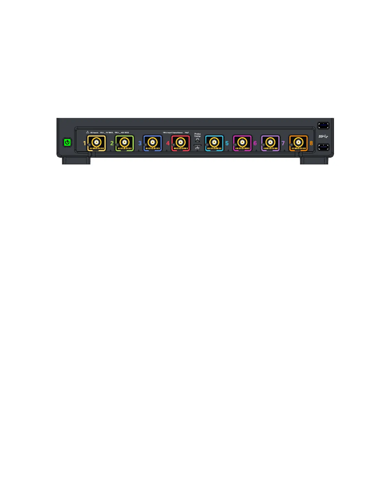
Front Panel Connectors
On the Infiniium MXR-Series oscilloscopes, the channel inputs, probe
compensation terminal, and ground lug appear on the lower part of the front
panel. Two USB 3.0 host ports are also located here.
Channel inputs
Your Infiniium oscilloscope comes with 10:1 500 MHz passive probes for each
analog input channel.
The AutoProbe interface also works with the InfiniiMax probing system.
See "Connecting Oscilloscope Probes" on page 30.
Probe compensation terminal
This terminal has a square wave signal that is used to adjust compensated passive
probes.
You can also output a DC level on this terminal using the Infiniium oscilloscope
application's Calibration Output dialog box (Utilities > Calibration Output...).
Figure 5 Front panel connectors