30 Keysight Infiniium MXR-Series Real-Time Oscilloscopes User's Guide
2 Getting Started
Connecting Oscilloscope Probes
The Keysight Infiniium MXR-Series oscilloscopes are not rated for Measurement
Category II, III, or IV.
For complete documentation on Keysight oscilloscope probes for your Infiniium
oscilloscope, see the Probe Resource Center at: keysight.com/find/prc
To connect oscilloscope probes:
1 Attach the probe connector to the desired oscilloscope channel or trigger input
using the probe instructions.
2 Connect the probe to the circuit of interest using the browser or other probing
accessories.
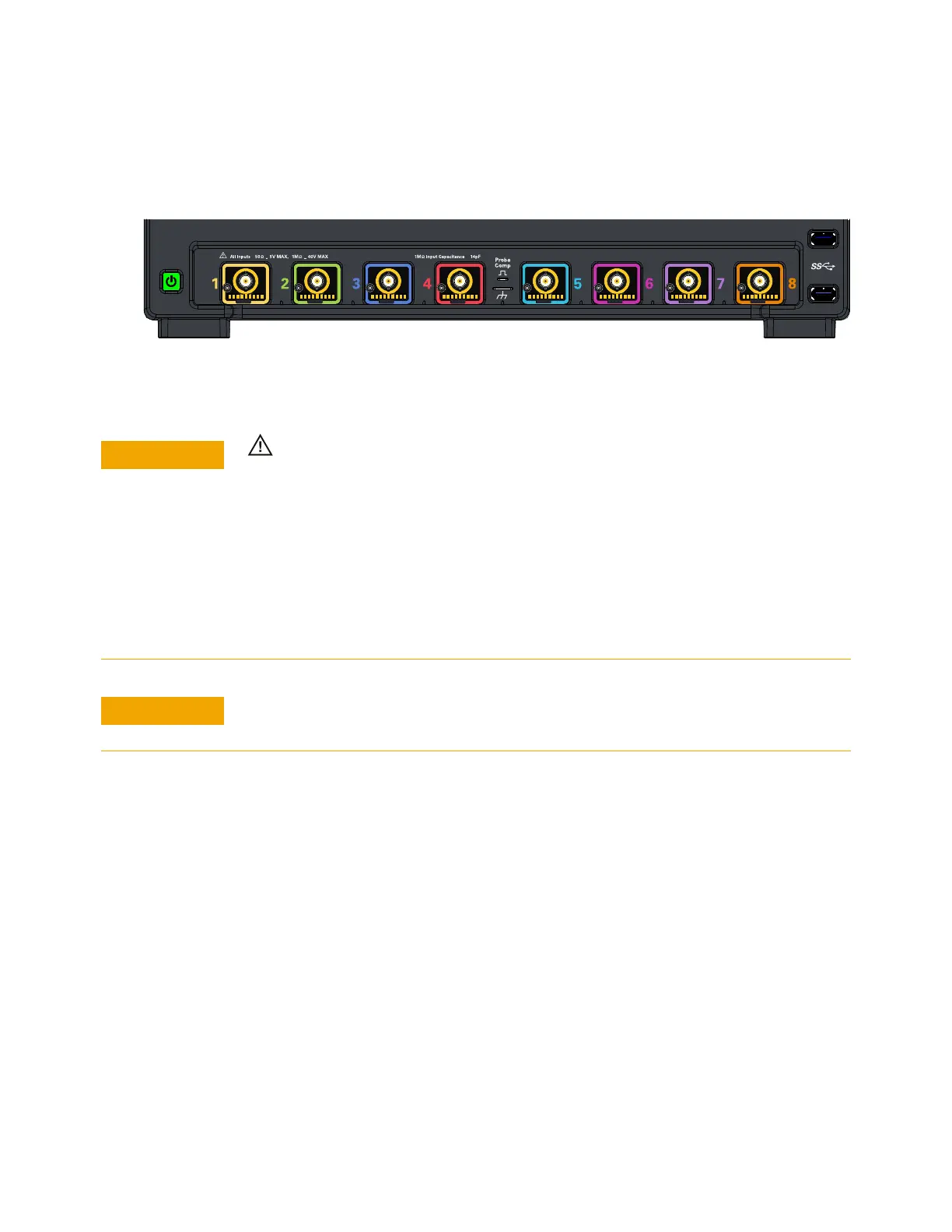
Figure 9 MXR-Series oscilloscope probe connectors
~
~
+ +
8 or 4 analog input channels where probes are connected
Maximum input voltage at analog inputs
Do not exceed the maximum input voltage rating.
The maximum input voltage for the 50 Ω input impedance setting is ±5 V.
The maximum input voltage for the 1 MΩ input impedance setting is 30 Vrms or
±40 Vmax (DC+Vpeak).
Probing technology allows for testing of higher voltages; the included N2873A 10:1
probe supports 300 Vrms or ±400 Vmax (DC+Vpeak). No transient overvoltage
allowed. Mains isolated circuits only.
When measuring voltages over 30 V, use a 10:1 probe.