EasyManuals Logo

Keysight Technologies IntegraVision PA2200 Series User Manual

Keysight Technologies IntegraVision PA2200 Series
178 pages
To Next Page IconTo Next Page
To Previous Page IconTo Previous Page
Page #122 background imageLoading...
Page #122 background image
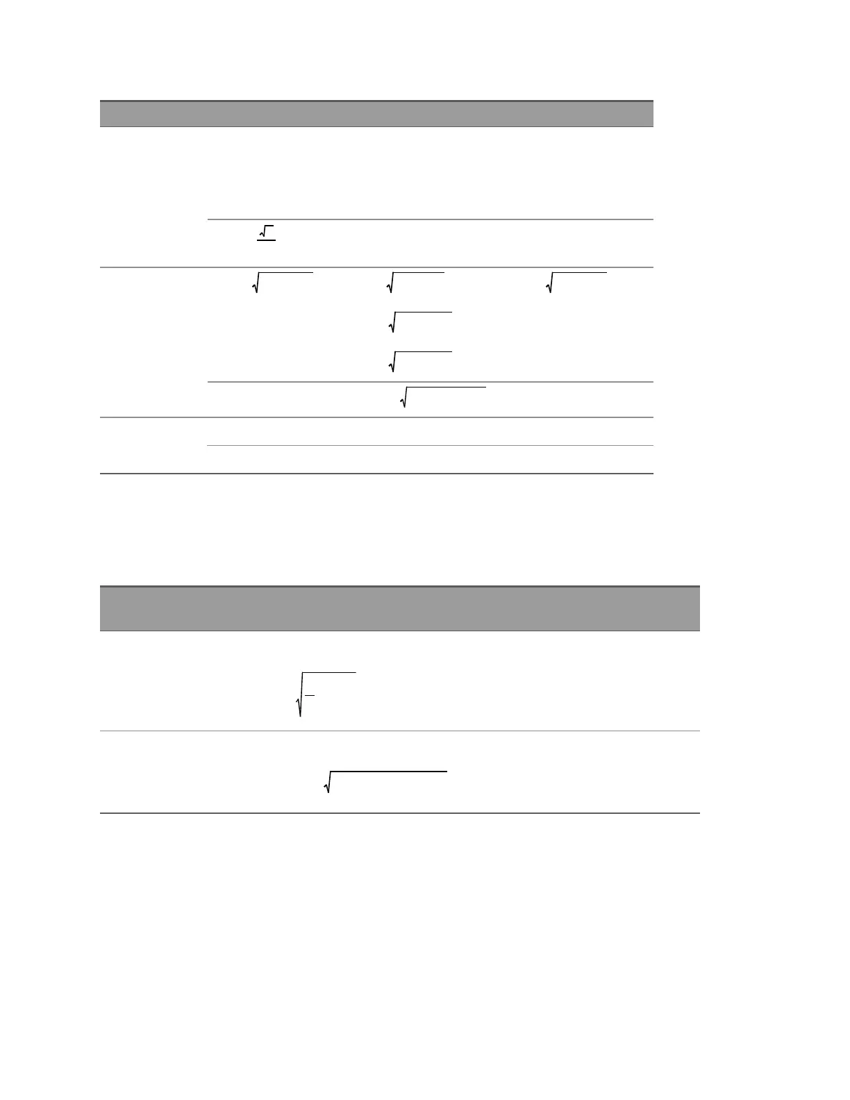
3P-3W-2M 3P-3W-3M 3P-4W-3M
Apparent Power
S V I= *
x x x
S V I= *
n1 1 1
S V I= *
n2 2 2
S V I= *
n3 3 3
S V I= *
x x x
S S S= +
sum
3
2
1 2
S S S S= + +
sum 1 2 3
Reactive Power*
Q S P= ±
x x x
2 2
Q S P=
1 1
2
1
2
Q S P=
2 2
2
2
2
Q S P=
3 3
2
3
2
Q S P= ±
x x x
2 2
Q Q Q= +
sum 1 2
Q S P=
sum sum sum
2 2
Q Q Q Q= + +
sum 1 2 3
Power Factor
λ P S= /
x x x
λ P S= /
sum sum sum
* For Reactive Power, the sign in front of the square root is + for lagging current and -1 for
leading current. The Voltage and Current CWA frequency must be within 5% to detect leading
or lagging.
For AC and DCmeasurement modes, adjust the formulas as shown below.
Measurement
Mode
Replace Real Power
DC Replace RMS(x) with AVG(x):
AVG x x=
N
n
N
n
1
= 0
1
Real power is DC power only:
P AVG v AVG i= ( )* ( )
x x x
AC Replace RMS(x) with RMS_AC(x):
( )
RMS AC x RMS x AVG x_ = ( ) ( )
2 2
Real power has DC component sub-
tracted out:
P AVG v i AVG v AVG i= ( * ) ( ) * ( )
x x x x x
120 Keysight IntegraVision PA2200 Series Power Analyzers Operating and Service Guide

Table of Contents

Questions and Answers:

Question and Answer IconNeed help?

Do you have a question about the Keysight Technologies IntegraVision PA2200 Series and is the answer not in the manual?

Keysight Technologies IntegraVision PA2200 Series Specifications

General IconGeneral
BrandKeysight Technologies
ModelIntegraVision PA2200 Series
CategoryMeasuring Instruments
LanguageEnglish

Related product manuals