Keysight PXIe Chassis Family User Guide 99
Front Panel Trigger Port Configuration Guidelines Configuring the PXI Trigger Bus
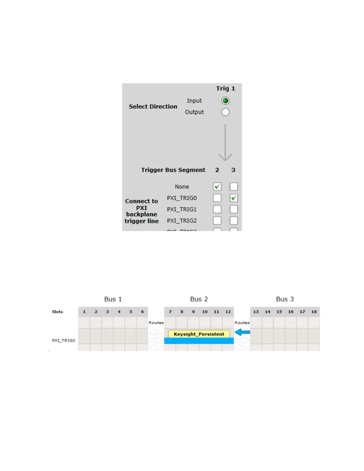
The following figure shows a simpler configuration, in which only PXI-TRIG0 on
Trigger Bus Segment 3 receives the incoming Trigger Port signal:
This configuration is silently ignored in situations where you also configure a
route on the same trigger line from Trigger Bus Segment 3 to Trigger Bus
Segment 2, as shown in the following example of the Connection Expert Chassis
Trigger tab:
If you have a route from Trigger Bus Segment 3, you cannot configure a Front
Panel Trigger Port signal on that trigger line on Bus Segment 3. If you attempt
such a configuration, the check box specification shown above is silently ignored
and the input trigger signal is not copied to PXI TRIG0 Bus Segment 3.
Figure 49 M9019A SFP example with Trig 1 only connected to PXI_TRIG0 on Segment 3..
Figure 50 Connection Expert example showing a route on PXI_TRIG0 from Segment 3 to Segment 2.