Keysight NFA Series Noise Figure Analyzers Service Guide 145
RF Section Troubleshooting (N8973B, 74B, 75B Analyzers)
Troubleshooting
If this power level is incorrect, the following assemblies need to be verified in
the order listed using the 50 MHz internal calibrator signal. Be sure the 50 MHz
calibrator is turned on Input/Output, RF Calibrator, 50 MHz when verifying the
performance.
1. A16 Reference Assembly
2. A14 L.O. Synthesizer
3. A15 Front End Control Assembly
4. A9 Input Attenuator A
5. A10 Input Attenuator B
6. A11 Low Band Switch
7. A12 YTF Preselector
8. A13 RF Front End Assembly
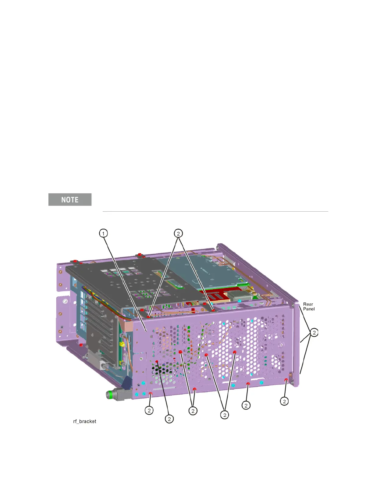
Figure 4-4 Remove the Side Chassis
In order to gain access to the front end components, remove the side
chassis
(1) by removing the 10 screws (2). Refer to Figure 4-4.