168 Keysight NFA Series Noise Figure Analyzers Service Guide
RF Section Troubleshooting (N8973B, 74B, 75B Analyzers)
Troubleshooting
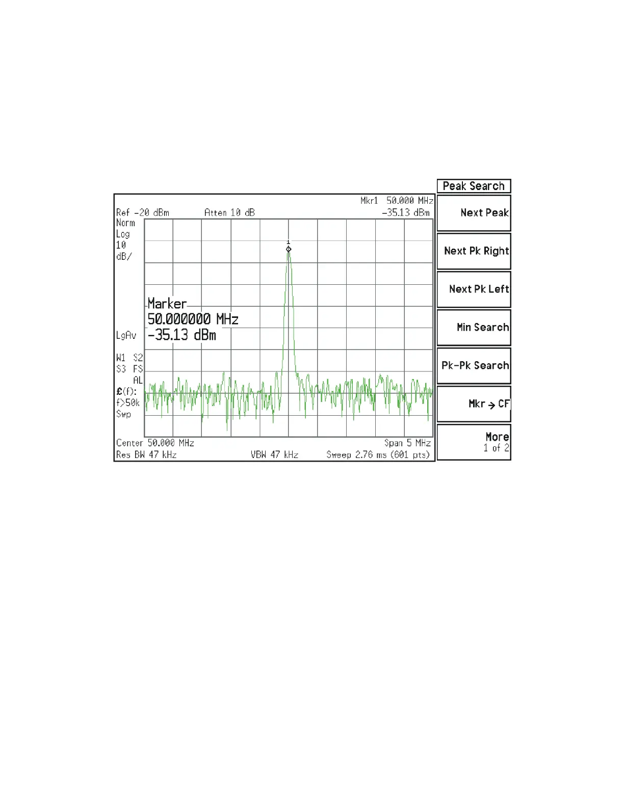
When the analyzer is tuned to a center frequency of 50 MHz, the Low Band
switch should have minimal loss. Press Input/Output, RF Calibrator, 50 MHz,
AMPTD, Attenuation, Mech Atten, 10 dB on the analyzer. Measure the 50 MHz
calibrator signal on the output of A11J2 using a functioning Spectrum
Analyzer. The level should be −35 dBm ± 5 dB as shown in Figure 4-18.
Figure 4-18 50 MHz Calibrator Signal at Output of W3 Cable
If the power level is incorrect the most probable cause is the low band switch
assembly. Reconnect W3 cable.
The following Low Band path items have been verified in the RF section:
— 50 MHz Calibrator signal power level from the A16 Reference Assembly
— 1st L.O. power level from the A14 L.O. Synthesizer
— Switch control logic from the A15 Front End Control Assembly to:
• Input Attenuator A
• Input Attenuator B
•Low Band Switch
• Front End Assembly
— Input Attenuator A power level check
— Input Attenuator B power level check
— Low Band Switch logic and power level check