Keysight NFA Series Noise Figure Analyzers Service Guide 171
RF Section Troubleshooting (N8973B, 74B, 75B Analyzers)
Troubleshooting
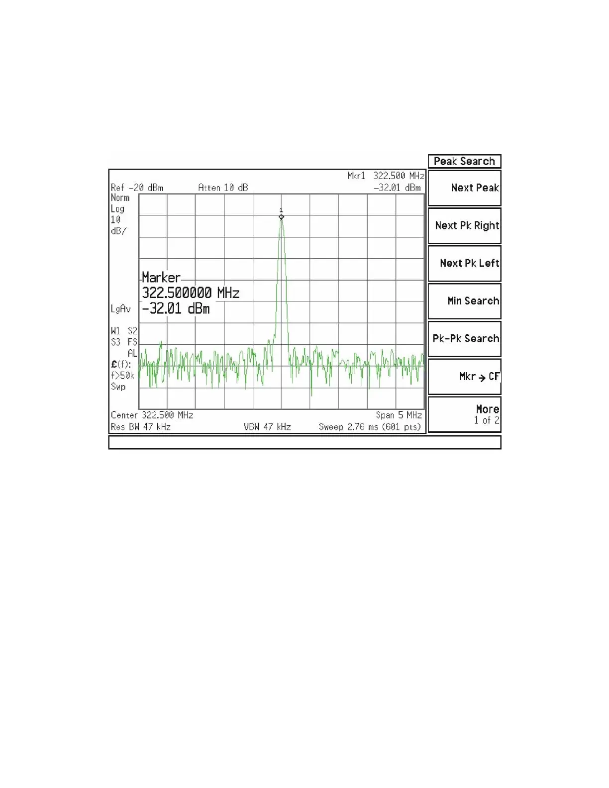
Connect A13J7 output to a functioning spectrum analyzer and verify the
322.5 MHz intermediate frequency is measuring −32 ± 4 dB as shown in Figure
4-20.
Figure 4-20 322.5 MHz Intermediate Frequency
If this power level is correct the entire RF section is operating correctly in high
band. If this power level is incorrect verify the following assemblies in the order
listed using the 4.8 GHz internal calibrator signal.
1. A16 Reference Assembly
2. A14 L.O. Synthesizer
3. A15 Front End Control Assembly
4. A9 Input Attenuator A
5. A10 Input Attenuator B
6. A11 Low Band Switch
7. A12 YTF Preselector
8. A13 RF Front End Assembly