Keysight NFA Series Noise Figure Analyzers Service Guide 237
Front End Control Troubleshooting
A15 Front End Control Assembly Troubleshooting
3. Connect the E4410-60115 RF Front End Troubleshooting board to the A15
Front End Control board using the E4410-60157 attenuator control cable.
When connecting the attenuator control cable, E4410-60157, note that
one end has two 10-pin connectors with one connector extending beyond
the other. The shorter connector is marked with a red stripe. Connect the
end with the 20-pin connector to A15J800. Connect the two 10-pin
connectors to either J3 or J4 of the RF Front End Troubleshooting board
based upon the EXA’s frequency range as described below:
4. If the NFA is an N8973B, 74B, or 75B, also connect the Low Band Switch
Control Cable, E4410-60160 between A15J700 and J2 of the RF Front End
Troubleshooting board. Do not connect this cable if the model is an
N8976B.
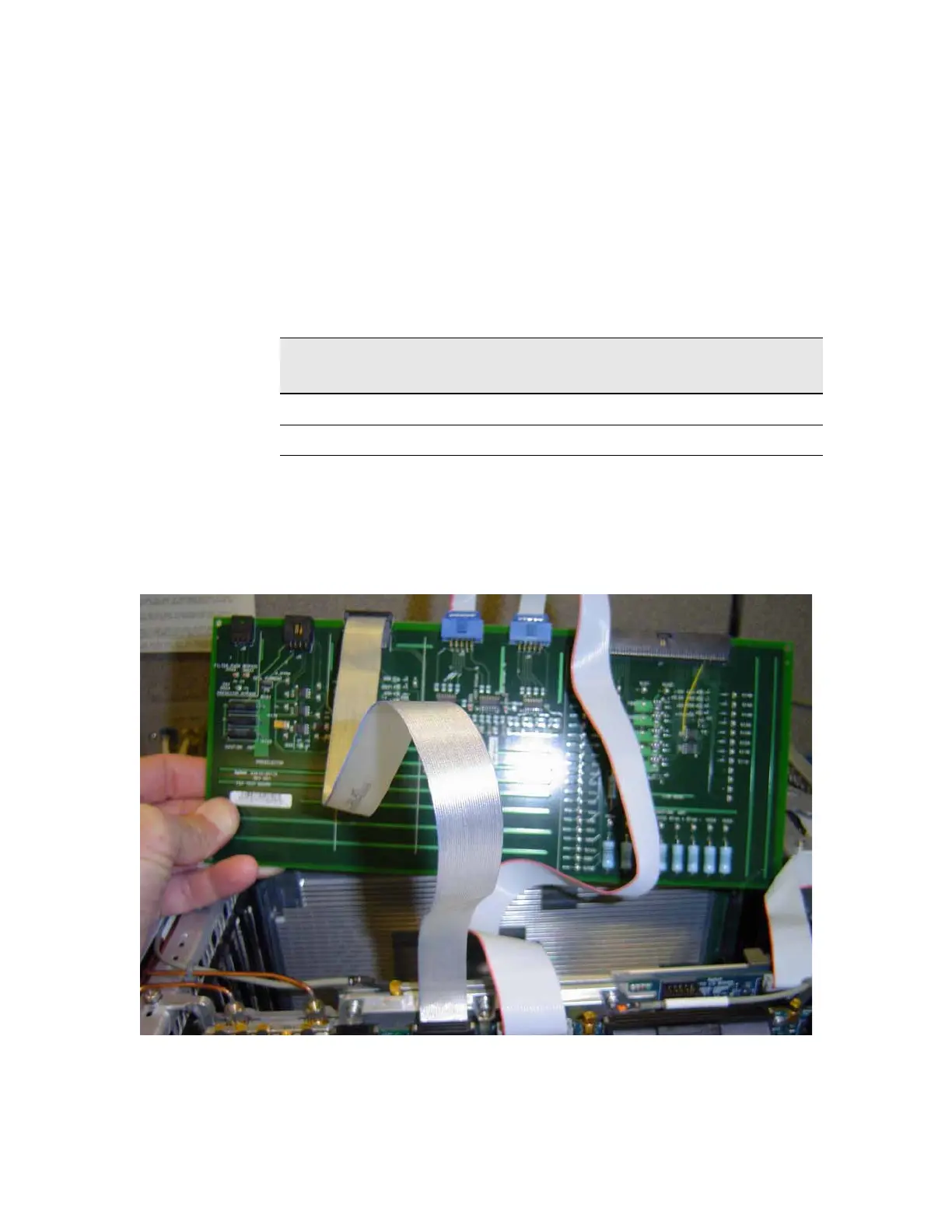
Figure 6-4 RF Front End Troubleshooting Board
Table 6-2 EXA Frequency Range
Model Shorter 10-pin connector
(marked with red stripe)
Longer 10-pin connector
N8973B, 74B, 75B J3 J4
N8976B J4 J3